 English
 русский

Slider spring hength and strength calculation
Processing size:
1. ØD2=ØD+2
2. Ll = total spring length (L) - preload value of spring (N) - slider core pulling distance (L2)
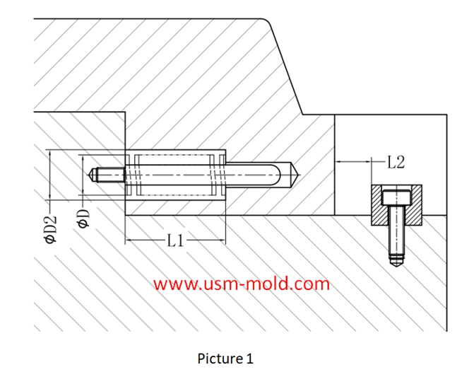
Spring length calculation: (refer to picture 1 for length calculation)
★L≥H/(36%(compression percentage)-10%(pre-compression percentage)
Assuming the core pulling distance (L2)=15m, the total length of the spring L≥15/(36%-10%)=15/0.26=57.7
As we can see that the total length of the spring (L) should be taken as 60mm
Spring hole depth L1=L-L*10%-L2=60-60*10%-15=39mm
Strength requirements of the slider spring:
1. When the spring is applied to the core pulling of the slider, the load strength must be checked;
2. The weight of the slider on the top side must be kept within 2/3 of the maximum load of the spring; the weight of other sliders must be kept within the maximum load of the spring;
3. When the same slider uses multiple springs, the maximum spring load of the slider is the sum of the loads of all springs;
4. When calculating the maximum load of the slider spring, the compression amount should be in the pull-out state of the slider;
The spring load is calculated as follows:
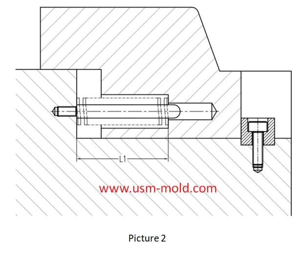
Picture 2:
1. The slider is in the extracted state, so the length of the spring after being compressed is L1;
2. Assume that the free length of the spring is L;
Calculation way of spring load: load = spring constant X compression
That is: load = spring constant X (L-L1)
The spring constant can be obtained from the standard parts data of the corresponding brand (such as MISUMI);

_20250310164515A048.webp "Voice Operated Switch Mold")

Venting system of plastic injection mold introduction
Feb 27, 2022Hello everyone, thanks for attention. We’ve discussed about the temperature control system earlier, now we are going to talk about the mold venting information in following 11 articles, from the...view
The principle of mold temperature balance in plastic mold cooling system design
Feb 21, 2022The principle of mold temperature balance: 1. Due to the complexity of the plastic parts and mold structure, it is difficult to make the temperature of the mold completely consistent, but should be...view
USM Blogo Opening
Oct 27, 2021Hello everyone! Our blog is open today, it is very glad to have the opportunity to meet you here, welcome to visit us whenever you need. USM is a professional plastic injection mold and molding...view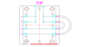
Different treatment of plastic injection mold cooling system principles
Feb 22, 2022Different treatment principle: 1. The mold temperature is different according to the different plastics, when the plastic requires the molding temperature of the mold to be ≥80°C, the mold must be...view
What is Ejection Molding?
Dec 28, 2021The process to get injection molded products is called injection molding, or called injection. Injection molding is an important method in polymer molding processing, it is characterized by a short...view
Controling method of plastic injection mold temperature
Feb 15, 2022Except for heat radiation and heat convection from the mold, most of the heat bring into the mold by the plastic needs to be taken out of the mold by the circulating heat transfer medium by heat...view