 English
 русский

Key points of plastic injection mold runner system
The sub-runner is a transitional channel between the main runner and the gate, as the sub-runner is the longgest part of gating system, so it is very important to enhance the parts quality and improve the productivity by reducing sub-runner process and flow resistance.
Sub-runner requirements:
① Bring the air in the gating system and the cold material at the front side of the melt into the cavity as less as possible to improve the molding quality.
②The runner resistance to the melt should be small, and the volume flow rate should be large to reduce the pressure and temperature loss when the melt flows through the runner.
③The solidification time of the runner should be later than the solidification time of the melt in the cavity to facilitate feeding.
④Ensure that the melt enters each cavity or every corner of the same cavity quickly and evenly.
⑤ The length of the runner should be as short as possible, and its volume should be as small as possible.
⑥The shape and size should be convenient for processing and tool selection.
⑦The upper-level runner is 10%~20% larger than the next-level runner.
Factors affecting the sub-runner design:
①The geometric shape, wall thickness, size, stability, internal quality and appearance quality requirements of plastic parts.
②The variety of plastics, that is the fluidity, melting temperature and melting temperature range, solidification temperature and shrinkage rate of the plastic.
③The pressure, heating temperature and injection speed of the injection molding machine.
④ Falling off method of main runner sub runner.
⑤The cavity layout, the gate location and type.
Key points of sub-runner design:
Cross-sectional area: as small as possible under the conditions of the injection process.
Distribution: compact and symmetrical, minimize the total area of the forming area.
Shape: The ratio of cross-sectional area to perimeter is as big as possible.
Length: as short as possible; the length of the runners of each cavity should be as equal as possible.
Steering: as few times as possible and rounded transitions.
Roughness of the inner surface: It is not necessary to be very light, so that the outer layer of the material flow forms a cooling layer for heat preservation, Ra=0.8~1.6μm.
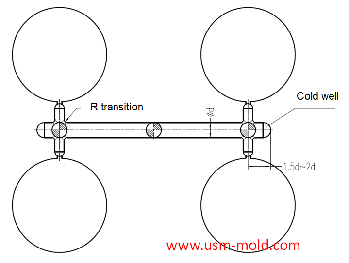
Condensate ejection: This is particularly desirable when a sprue puffier is used when sub-runner is in cavity side or it is long.
The end of the sub-runner should be provided with a cold well and exhausting-slot .


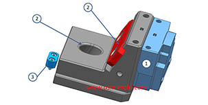
Slider designing tips 1
Aug 3, 20221. After the slider core pulls out, the length of staying in the guide pin slot should not be less than 2/3 of the total length of the slider, for special cases, the slider slot can be partially...view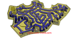
Plastic cooling factors by injection parameter
Feb 10, 20221. Plastic parts design: mainly for the wall thickness of plastic products. The thicker thickness of the product, the longer the cooling time. Generally speaking, the cooling time is approximately...view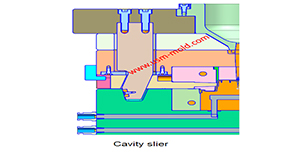
What is the side parting and core pulling mechanisms with their function?
May 31, 2022When there are holes, cavities or cores on the inside or outside of the injection-molded plastic parts that are different from the opening and closing directions of the mold, the plastic parts cannot...view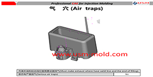
Reasons for making the exhaust system of the injection mold
Feb 28, 2022The gas in the injection mold includes not only the air in the cavity, but also the air in the gate and the decomposition gas generated by the plastic melt, and the steam which caused by plastic in...view_20250317090912A017.jpg)
Several common process of water-assisted injection molding introduction
May 24, 2022According to the design of the injection molding machine and the casting system, the corresponding melt-returning process of water-assisted injection molding can be roughly divided into two types: the...view
Plastic part ribs desigining
Jan 4, 2022The ribs function: The role of ribs is to improve the strength and rigidity of the plastic parts, prevent the plastic parts from being distorted and deformed, and will not cause the appearance of the...view