 English
 русский

Slider spring hength and strength calculation
Processing size:
1. ØD2=ØD+2
2. Ll = total spring length (L) - preload value of spring (N) - slider core pulling distance (L2)
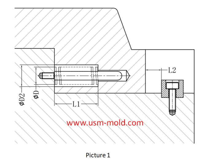
Spring length calculation: (refer to picture 1 for length calculation)
★L≥H/(36%(compression percentage)-10%(pre-compression percentage)
Assuming the core pulling distance (L2)=15m, the total length of the spring L≥15/(36%-10%)=15/0.26=57.7
As we can see that the total length of the spring (L) should be taken as 60mm
Spring hole depth L1=L-L*10%-L2=60-60*10%-15=39mm
Strength requirements of the slider spring:
1. When the spring is applied to the core pulling of the slider, the load strength must be checked;
2. The weight of the slider on the top side must be kept within 2/3 of the maximum load of the spring; the weight of other sliders must be kept within the maximum load of the spring;
3. When the same slider uses multiple springs, the maximum spring load of the slider is the sum of the loads of all springs;
4. When calculating the maximum load of the slider spring, the compression amount should be in the pull-out state of the slider;
The spring load is calculated as follows:
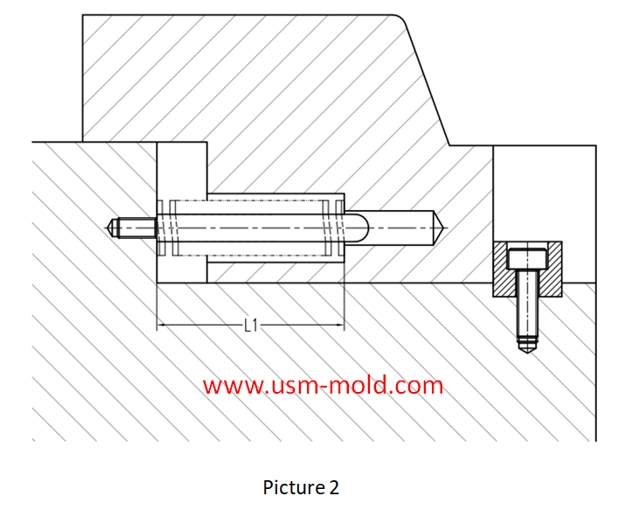
Picture 2:
1. The slider is in the extracted state, so the length of the spring after being compressed is L1;
2. Assume that the free length of the spring is L;
Calculation way of spring load: load = spring constant X compression
That is: load = spring constant X (L-L1)
The spring constant can be obtained from the standard parts data of the corresponding brand (such as MISUMI);


_20250311083139A052.webp "Transparent PC Injection Mold")
Venting system of plastic injection mold introduction
Feb 27, 2022Hello everyone, thanks for attention. We’ve discussed about the temperature control system earlier, now we are going to talk about the mold venting information in following 11 articles, from the...view
Plastic injection mold cooling system design notice
Feb 14, 2022Design notice of designing the cooling system: 1. Normal molds can be quickly cooled to obtain a shorter molding cycle, and precision molds can be slowly cooled with a mold temperature thermometer; 2....view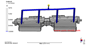
Plastic injection mold runner system design points
Jan 9, 2022When designing the gating system, Firstly, we should consider making the plastic melt fill the cavity with core side quickly to reduce pressure and heat loss; secondly, it should be economically...view
Temperature system of injection mold
Feb 8, 2022Hi everyone,the mold cooling time is the longest during injection, so the design of mold temperature system controlling is very important, we will talk about mold cooling, heating system in following...view
Banana gate of plastic injection mold runner system design
Feb 7, 2022In order to get the best injection quality, the gate type must be selected carefully, the coommon gate tyeps are: direct gate, side gate, pin-point gate, sub gate,valve gate of hot runner etc. Among...view
What is Plastic Injection Mold?
Dec 27, 2021The plastic mold is used for injection molding, it is assembled with cavity, core and side slider together, with ejection system and adjustments to produce plastic products by different shapes and...view