 English
 русский

Design principles of plastic injection mold runner system
1. Quality first
The design of the gating system has a big influence on part quality, firstly the gate should be set at the easiest part of the plastic part to be removed, and at the same time, the appearance of the plastic part should not be affected as much as possible. Secondly, the gate position and type will directly affect the molding quality of the plastic parts, an unreasonable gating system will cause the defects such as weld marks, poor filling, flow marks, and even lead to the mold failure.
2. Filling balance
In a single-cavity injection mold, the distance between the gate position and each part of the cavity should be as equal as possible, so that the melt fills all corners of the cavity at the same time; in a multi-cavity injection mold, the runner to each cavity should be as equa as possible, so the melt can fill all the cavities at the same time. In addition, the same plastic parts should be feed from the same position to ensure their interchangeability.
3. Smallest volume
The arrangement of the cavities should be as compact as possible, the flow of the gating system should be as short as possible, the cross-sectional shape and size of the runner should be reasonable, and the smaller the volume of the gating system the better, it has the following advantages:
①The less the heat and pressure loss of the melt in the gating system;
②The mold venting is better;
③The mold absorbds the heating less from gating system, the mold temperature control is easier;
④The shorter time of melt flows in the gating system, the mold cycle is shorter;
⑤The less aggregate in the gating system, the less plastic wasted;
⑥The mold size is smaller.
4. Shortest cycle
In the case of a mold with one cavity, it should be ensured that the melt fills all corners of the cavity in almost the same time; when a mold with multiple cavities, it should be ensured that each cavity is filled in almost the same time. In this way, the molding quality of the plastic parts can be guaranteed, and the injection cycle can be minimized. When designing the gating system, we must also try to reduce the resistance of the melt and increase the filling speed of the melt. The runner should reduce the bending, and the arc transition should be used as much as possible when turning. However, in order to reduce the resistance of the melt, it is often not advisable to polish the surface of the runner to a very low roughness, because the appropriate roughness can leave the cold material at the front of the melt on the wall of the runner (runner wall Equivalent to countless miniature cold slug holes). In general, the surface roughness Ra of the runner can be 0.8~1.6μm.
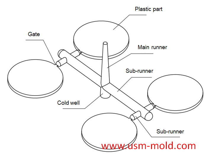
Typical gating system

_20250310164515A048.webp "Plastic Box Mould")

Pin-point gate of plastic injection mold runner system design
Jan 24, 2022In order to get the best injection quality, the gate type must be selected carefully, the coommon gate tyeps are: direct gate, side gate, pin-point gate, sub gate,valve gate of hot runner etc. Among...view_20250317091113A018.jpg)
The basic points of designing gas-assisted injection molding
Apr 17, 20221. Firstly, considering the suitable wall thickness areas needs to be injected and hollowed out, and then decide how to connect them with the gas channel; 2. The gas channel should be arranged in...view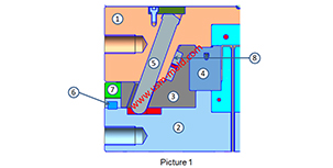
Slider of side core pulling mechanisum assembling
Jul 21, 2022The picture 1 shows a typical guide pin driven slider parting and core-pulling mechanism, we will talk about the composition and function of the lateral core-pulling mechanism. 1. Lateral forming...view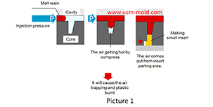
The main reasons for air trapping of plastic injecton mold
Mar 1, 2022During the injection molding process, the front end of the slight ribs may be air trapped and plastic burnt, and also cause the molded part may become black and carbonized. The mechanism of air...view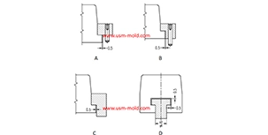
The T slot of slider and guider designing tips
Dec 18, 20231. The T slot of slot should be designed according to the picture 1, If there is a relatively high slider, the slider T slot is not high enough which will cause the center of gravity to be unstable,...view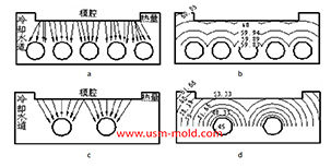
Factors affecting the cooling rate of parts by injection molding
Feb 9, 2022It should be shaped by cooling to get stable plastic part after plastic filling the cavity and core side, so most injection molds need to be equipped with cooling devices to make the mold temperature...view