 English
 русский

Design standard of exhaust slot
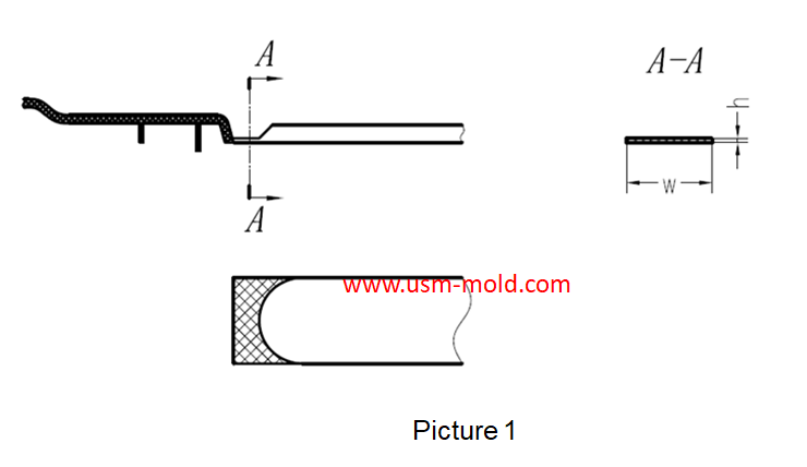
The exhaust system should ensure that the gas in the cavity is smoothly discharged, and also prevent the material from entering and exhausting channels from causing flashing of the product or blockage of the gas channel during mass production, most plastic mold factories and plastic mold suppliers only know that they need to open an exhaust slot, but they don’t how large is reasonable. So the cross-sectional size design at the entrance of the exhaust system is very important, in order to meet the above requirements, the inlet section of the exhaust system is usually designed as a gap with a larger aspect ratio (h/w) (see pictue 1), and the gap depth (exhaust gap or exhaust slot depth) h, which is less than the overflow value of the material into the mold is limited, generally 0.02-0.05mm; the gap width w is determined according to the gap depth H and the cross-sectional area A of the exhaust passage required to discharge the gas in the mold cavity during the filling time (w≥A /h).
The cross-sectional area A of the exhaust channel is calculated as follows: A=0.05V/N
In the formula: A exhaust channel cross-sectional area mm²
V—total volume of cavity and pouring system, cm³
n——the number of exhaust slots
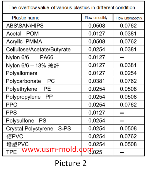
The overflow value is the smallest gap that the material can flow into, the overflow value of the molding material depends on the fluidity of the material determined by the material characteristics and process conditions. The better the fluidity, the smaller the overflow value, tThe overflow values of commonly used plastics and conventional molding conditions are shown in picture 2 in the following table.
Picure 3 shows the design standard of the exhaust slot, and picture 4 shows the wrong opening method of the exhaust slot.


Design Tips of Vacuum Venting Mold
Mar 30, 2022There are some regular venting way which are parting surface venting, insert venting, insert pin venting and well-ventilated steel, but there is a special way is vacumm venting, it will need vacumm...view
Temperature system of injection mold
Feb 8, 2022Hi everyone,the mold cooling time is the longest during injection, so the design of mold temperature system controlling is very important, we will talk about mold cooling, heating system in following...view
What is the side parting and core pulling mechanisms with their function?
May 31, 2022When there are holes, cavities or cores on the inside or outside of the injection-molded plastic parts that are different from the opening and closing directions of the mold, the plastic parts cannot...view
Different treatment of plastic injection mold cooling system principles
Feb 22, 2022Different treatment principle: 1. The mold temperature is different according to the different plastics, when the plastic requires the molding temperature of the mold to be ≥80°C, the mold must be...view
The difference between full shot and short shot of gas-assisted injection molding
Apr 13, 2022Gas-assisted injection molding can be divided into short shot and full shot. Short shot The short shot method is shown in picture 1, it is suitable for thick-walled plastic parts with low mold filling...view
Plastic part ribs desigining
Jan 4, 2022The ribs function: The role of ribs is to improve the strength and rigidity of the plastic parts, prevent the plastic parts from being distorted and deformed, and will not cause the appearance of the...view