 English
 русский

The main design points of the design of the plastic mold pouring system
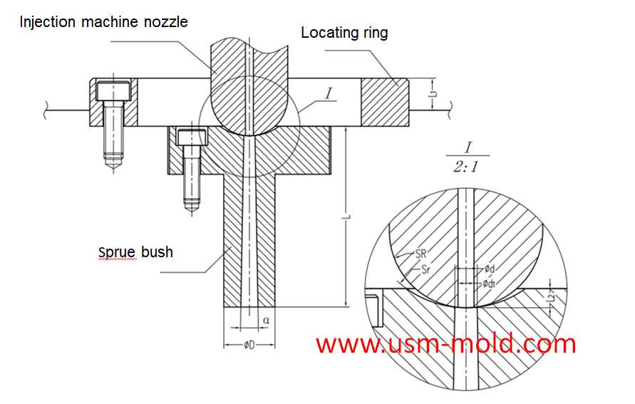
The main runner is the part where the molten plastic first passes when it is sprayed from the injection nozzle, and it is coaxial with the injection nozzle, because of repeated contact and collision with molten plastics and injection nozzles, they are generally not directly installed on the cavity, but are made into detachable sprue bush, which are fixed on the cavity with screws or matching forms, the basic structure of the main runner and the installation type is shown in the following picture.
From the perspective of reducing pressure and heat loss, the conical shape is the most superior sprue shape, the basic size of the main runner usually depends on the following two aspects.
1. The type of plastic used, the quality of the molded plastic part and the thickness of the wall. Generally speaking, for plastics with poor fluidity, the sprue size should be appropriately bigger, and for plastics with good fluidity, the sprue size should be appropriately smaller;
2. The relationship between the geometric parameters of the injection molding machine nozzle and the size of the main runner, in order to prevent the nozzle from contacting the sprue bushing and causing a gap, the spherical radius of the sprue bushing should be 2~5mm bigger than the radius of the nozzle ball, the main runner should have a smooth surface, and the end should be equipped with a cold slug well to prevent the cold slug from flowing into the cavity and affecting the part quality.
In the injection mold, the sprue is in the sprue bushing, and the sprue bushings can be divided into two types: two-plate mold sprue bushing and three-plate mold sprue bushing, the main runner can be divided into two-platen main runner and three-platen main runner according to different mold structures.
The main points of the main channel design are as follows:
1. Using a tapered hole of α=1°~4° to take the condensate of the gate (the cone angle is too big, the injection speed is slow, and the vortex is formed); the inner wall of the tapered hole is rough Ra=0.63μm; the big end of the tapered hole has a transition from R1 to R2 Fillet (to reduce the flow resistance when the material flow turns).
2. The concave spherical surface of the sprue push coincides with the convex spherical surface of the injection machine nozzle: Sr=Sr+ (0.5~2mm injection machine nozzle head radius); d=d1+(0.5~1)m (d1 injection machine nozzle inner diameter) end surface concave spherical depth L2=3~5mm.
3. The outer diameter of the positioning ring D1 is in clearance fit with the positioning hole of the injection machine; the thickness of the locating ring is L1=5-10mm.
4. The length L of the sprue push should be as short as possible (L is too big, the pressure loss is too big, and the temperature of the material is too big);
5. The sprue push material is SKD61 hardened, and the hardness should be less than that of the nozzle of the injection machine.


Plastic injection mold heating
Feb 16, 2022When the plastic injection molding process requires the mold temperature to be above 80°C, a temperature adjustment system with heating function must be provided in the mold. In addition,...view
Hydraulic diameter conversion of runners in plastic mold gating system design
Jan 13, 2022Hydraulic diameter refers to 4 times the ratio of the flow cross-sectional area to the perimeter, as the wall shear stress of non-circular pipes is not even distributed along the surrounding walls,...view
Design principles for wall thickness of plastic products
Jan 3, 2022The principles of wall thickness design for plastic parts are as follows: 1. Making the wall thickness even is the first principle of plastic part design, it can make filling, cooling and shrinking...view
Limitations of gas-assisted injection molding technology
Apr 25, 2022Gas-assisted injection molding technology has obvious advantages in thick wall thickness and pipe parts, but this technology still has many limitations, which are mainly reflected in the following...view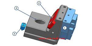
Slider designing tips 1
Aug 3, 20221. After the slider core pulls out, the length of staying in the guide pin slot should not be less than 2/3 of the total length of the slider, for special cases, the slider slot can be partially...view
Slider designing tips 2
Nov 22, 20239. The molding parting surface of the slider molding should be made as a shut-off surface as possible, and the width of the shut-off part should be at least 8mm, and do not make a shut-off surface;...view