 English
 русский

Hydraulic diameter conversion of runners in plastic mold gating system design
Hydraulic diameter refers to 4 times the ratio of the flow cross-sectional area to the perimeter, as the wall shear stress of non-circular pipes is not even distributed along the surrounding walls, only the average value of the surrounding walls can be calculated.
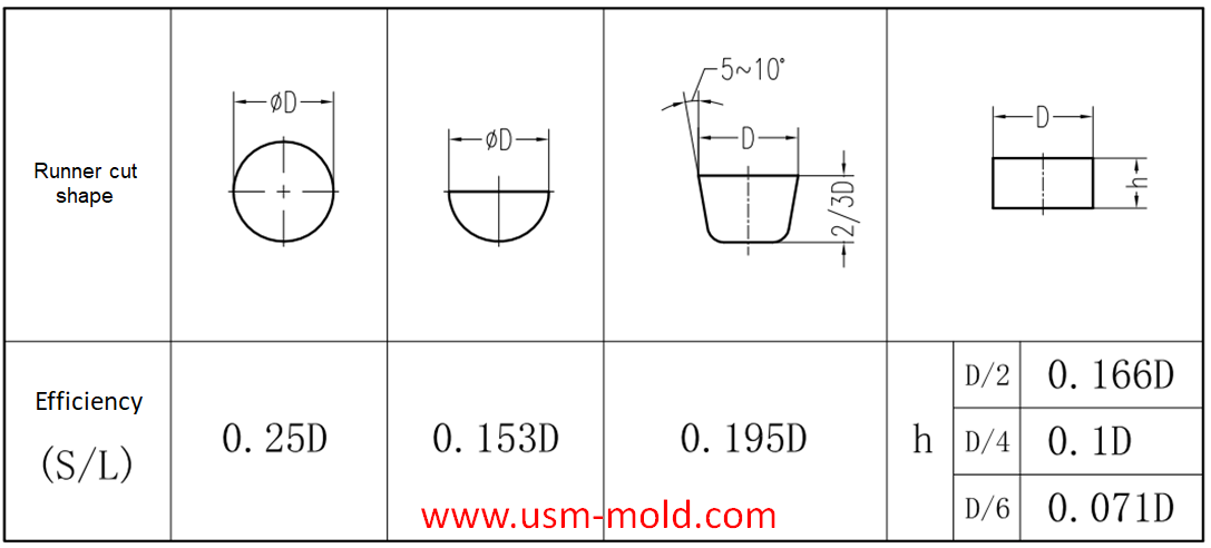
The main cross-sectional shapes of the shunt: round, trapezoidal and rectangular, in order to reduce the pressure heat loss in the runner, the cross-sectional area of the runner should be maximized, and the internal surface area for heat dissipation should be the smallest.
The efficiency of the runner is expressed by the ratio of the cross-sectional area S of the runner to its cross-sectional circumference L.
Splitter efficiency (hydraulic radius) n=cross-sectional area/cross-sectional circumference=S/L
Hydraulic diameter=4n=4S/L
From the above information, we can see the flow efficiency of different cross-section runners, round and trapezoidal cross-sections are the preferred runners. The size of the runner is usually selected based on the diameter of the circular runner (equal to the hydraulic diameter); when other cross-section flow channels are used, the hydraulic diameter must be converted so that the flow efficiency can meet the calculation requirements (see the example below) ).
Example: It is calculated that a product needs a 8m hydraulic diameter runner, and a semicircular runner is now used; what size of semicircle is more reasonable?
Hydraulic diameter=4n=4S/L=(4*(πr²)/2)/(π*r+2r)=8
Radius r=8*(π+2)/(2π)=6.55
Diameter D=2*r=6.55*2=13.1
Answer: A semicircular runner with a diameter of about 13m is more suitable.


_20250310164515A048.webp "Voice Operated Switch Mold")
Plastic injection mold runner system design
Jan 16, 2022The gate is the connecting part between the runner and the cavity, and is also the end part of the injection mold gating system, the molten plastic enters the cavity and core side through the gate...view
USM Blogo Opening
Oct 27, 2021Hello everyone! Our blog is open today, it is very glad to have the opportunity to meet you here, welcome to visit us whenever you need. USM is a professional plastic injection mold and molding...view
Comparison of water-assisted and gas-assisted injection molding
May 19, 2022Comparing with water-assisted injection molding technology and gas-assisted injection molding technology, the fundamental difference is the nature of the auxiliary molding media used. One is liquid...view
Gas-assisted Injection Molding Equipment
Apr 10, 2022The gas-assisted equipment includes a gas-assisted control part and a nitrogen generator, it is special and seperate system of the injection molding machine, and its only interface with the injection...view
Parting surface venting of runner system
Mar 10, 2022There are a large amount of gas in the main and sub channel, these gas are discharged through the pull rod (push rod) during injection processing, a part of gas come out from exhaust slot on parting...view
Different treatment of plastic injection mold cooling system principles
Feb 22, 2022Different treatment principle: 1. The mold temperature is different according to the different plastics, when the plastic requires the molding temperature of the mold to be ≥80°C, the mold must be...view