 English
 русский

The main design points of the design of the plastic mold pouring system
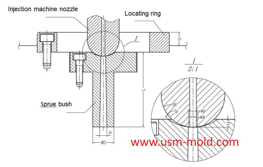
The main runner is the part where the molten plastic first passes when it is sprayed from the injection nozzle, and it is coaxial with the injection nozzle, because of repeated contact and collision with molten plastics and injection nozzles, they are generally not directly installed on the cavity, but are made into detachable sprue bush, which are fixed on the cavity with screws or matching forms, the basic structure of the main runner and the installation type is shown in the following picture.
From the perspective of reducing pressure and heat loss, the conical shape is the most superior sprue shape, the basic size of the main runner usually depends on the following two aspects.
1. The type of plastic used, the quality of the molded plastic part and the thickness of the wall. Generally speaking, for plastics with poor fluidity, the sprue size should be appropriately bigger, and for plastics with good fluidity, the sprue size should be appropriately smaller;
2. The relationship between the geometric parameters of the injection molding machine nozzle and the size of the main runner, in order to prevent the nozzle from contacting the sprue bushing and causing a gap, the spherical radius of the sprue bushing should be 2~5mm bigger than the radius of the nozzle ball, the main runner should have a smooth surface, and the end should be equipped with a cold slug well to prevent the cold slug from flowing into the cavity and affecting the part quality.
In the injection mold, the sprue is in the sprue bushing, and the sprue bushings can be divided into two types: two-plate mold sprue bushing and three-plate mold sprue bushing, the main runner can be divided into two-platen main runner and three-platen main runner according to different mold structures.
The main points of the main channel design are as follows:
1. Using a tapered hole of α=1°~4° to take the condensate of the gate (the cone angle is too big, the injection speed is slow, and the vortex is formed); the inner wall of the tapered hole is rough Ra=0.63μm; the big end of the tapered hole has a transition from R1 to R2 Fillet (to reduce the flow resistance when the material flow turns).
2. The concave spherical surface of the sprue push coincides with the convex spherical surface of the injection machine nozzle: Sr=Sr+ (0.5~2mm injection machine nozzle head radius); d=d1+(0.5~1)m (d1 injection machine nozzle inner diameter) end surface concave spherical depth L2=3~5mm.
3. The outer diameter of the positioning ring D1 is in clearance fit with the positioning hole of the injection machine; the thickness of the locating ring is L1=5-10mm.
4. The length L of the sprue push should be as short as possible (L is too big, the pressure loss is too big, and the temperature of the material is too big);
5. The sprue push material is SKD61 hardened, and the hardness should be less than that of the nozzle of the injection machine.

_20250310164515A048.webp "PLC Controller Shell Mold")
Plastic injection mold runner system design points
Jan 9, 2022When designing the gating system, Firstly, we should consider making the plastic melt fill the cavity with core side quickly to reduce pressure and heat loss; secondly, it should be economically...view
Vacuum venting mold design for plastic molded parts
Mar 23, 2022There are some regular venting way which are parting surface venting, insert venting, insert pin venting and well-ventilated steel, but there is a special way is vacumm venting, it will need vacumm...view
Plastic cooling factors by injection parameter
Feb 10, 20221. Plastic parts design: mainly for the wall thickness of plastic products. The thicker thickness of the product, the longer the cooling time. Generally speaking, the cooling time is approximately...view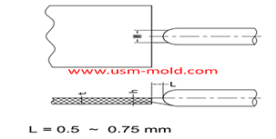
Plastic injection mold runner system design
Jan 16, 2022The gate is the connecting part between the runner and the cavity, and is also the end part of the injection mold gating system, the molten plastic enters the cavity and core side through the gate...view
Key points of gas-assisted injection molding process
Apr 20, 2022Gas injection parameters The gas-assisted control part is a device that controls the gas pressure in each stage, the gas-assisted parameters have only two values: gas injection time (seconds) and gas...view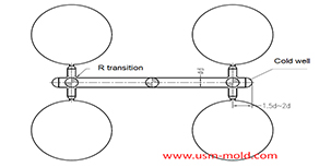
Key points of plastic injection mold runner system
Jan 12, 2022The sub-runner is a transitional channel between the main runner and the gate, as the sub-runner is the longgest part of gating system, so it is very important to enhance the parts quality and improve...view