 English
 русский

Plastic injection mold runner system design
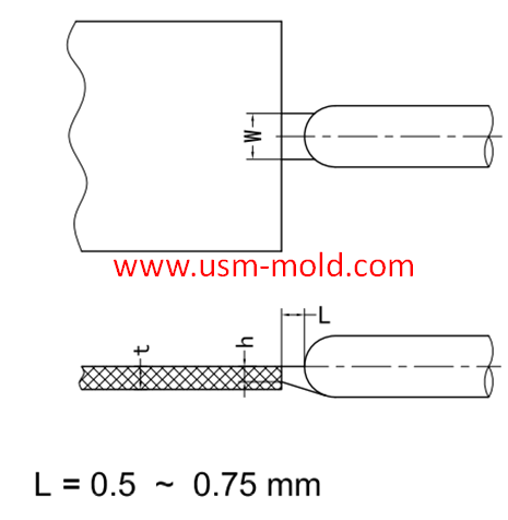
The gate is the connecting part between the runner and the cavity, and is also the end part of the injection mold gating system, the molten plastic enters the cavity and core side through the gate directly. The function of the gate is make the molten plastic coming from the runner enter and fill the cavity with core by fast speed, after the cavity with core are filled with plastic, the gate can be cooled quickly and sealed to prevent the hot material in the cavity from flowing material.
The gate design is related to factors such as the part shape, the cross-sectional size of the part, the plastic performance, the mold structure and the injection process parameters. The gate cross-sectio should be small and the length should be short, so as to increase the material flow speed, fast cooling and sealing to separate the plastic parts, and the gate marks are not obvious.
The gate is a key part of the gating system, the gate location, type and size have a big influence on the plastic parts quality, the quality defects of plastic parts, such as air trapping, shrinkage, water trapping, decomposition, washout, deformation, etc., are often caused by unreasonable gate design. The gate is the smallest part of the entire gating system (except for the direct gate of the sprue type) in many cases.
The design content of the gate includes the following 3 points:
①Select the gate location
②Determine the gate type
③Determine the gate size
We will talk about how to determine the location of the gate in following article.


_20250310164515A048.webp "Plastic Box Mould")
Plastic injection mold runner system design
Jan 16, 2022The gate is the connecting part between the runner and the cavity, and is also the end part of the injection mold gating system, the molten plastic enters the cavity and core side through the gate...view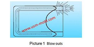
Gas-assisted injection molding product defects and solutions
Apr 28, 2022Common defects and solutions of gas-assisted injection moulding: 1. Gas blows out the melt like in picture 1. Reason: insufficient pre-filled amount. When the plastic part is a locally thickened...view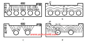
Factors affecting the cooling rate of parts by injection molding
Feb 9, 2022It should be shaped by cooling to get stable plastic part after plastic filling the cavity and core side, so most injection molds need to be equipped with cooling devices to make the mold temperature...view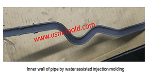
Comparison of water-assisted and gas-assisted injection molding
May 19, 2022Comparing with water-assisted injection molding technology and gas-assisted injection molding technology, the fundamental difference is the nature of the auxiliary molding media used. One is liquid...view
What is Plastic Injection Mold?
Dec 27, 2021The plastic mold is used for injection molding, it is assembled with cavity, core and side slider together, with ejection system and adjustments to produce plastic products by different shapes and...view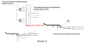
Design standard of exhaust slot
Mar 3, 2022The exhaust system should ensure that the gas in the cavity is smoothly discharged, and also prevent the material from entering and exhausting channels from causing flashing of the product or blockage...view