 English
 русский

Insert pin of vengting design for molded parts
Insert pin of venting:
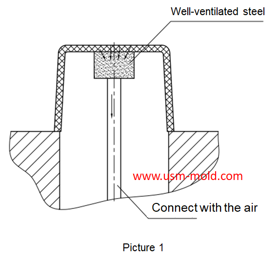
It is difficult to make exhaust slot when end runner is not in parting surface during injection, and there is no matching gap available, but we could make the venting pin at end of runner side, and also the exhasut slot will be connected with the air in outside as the venting system, there are some tips for making the insert pin as following:
1. The venting pin should fixed with the mold by H7/g6;
2. There should be an exhaust slot on the side of the venting pin and connect with the air (as shown in picture 1);
3. It will be used venting pin when air trapping position is fixed, but it will be better to use venting insert if the air trapping position is changing in local;
4. The sealing area of insert pin will be made according to the size of insert pin, and the length of sealing is 10-20mm, then it can clearance later;
5. The top of insert pin will make 3 snaps to make venting, and the depth is 0.02~0.05mm;
6. Insert pin is changed by injector pin.


Plastic injection mold runner system design points
Jan 9, 2022When designing the gating system, Firstly, we should consider making the plastic melt fill the cavity with core side quickly to reduce pressure and heat loss; secondly, it should be economically...view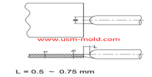
Plastic injection mold runner system design
Jan 16, 2022The gate is the connecting part between the runner and the cavity, and is also the end part of the injection mold gating system, the molten plastic enters the cavity and core side through the gate...view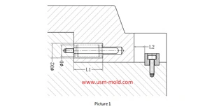
Slider spring hength and strength calculation
Apr 22, 2024Processing size: 1. ØD2=ØD+2 2. Ll = total spring length (L) - preload value of spring (N) - slider core pulling distance (L2) Spring length calculation: (refer to picture 1 for length calculation)...view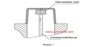
Well-ventilated steel of venting design for molded parts
Mar 14, 2022Well-ventilated steel is a sintered alloy, iIt is a porous material sintered with spherical particle alloys, the pore size is 7-10μm and the strength is poor, but the texture is loose which allow the...view
Gas-assisted Injection Molding Equipment
Apr 10, 2022The gas-assisted equipment includes a gas-assisted control part and a nitrogen generator, it is special and seperate system of the injection molding machine, and its only interface with the injection...view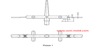
Parting surface venting of runner system
Mar 10, 2022There are a large amount of gas in the main and sub channel, these gas are discharged through the pull rod (push rod) during injection processing, a part of gas come out from exhaust slot on parting...view