 English
 русский

The design principle of the exhaust slot
The exhaust system of plastic molds is also very important, if the product has air trapping or exhaust system is not suitable will have a big impact on injection molding production and product quality, especially for predeformation mold, the part size will be different if there is air trapping inside mold, which will cause instability during production.
We must follow the following principles when making the mold exhaust slot:
1. The exhaust must be rapid and complete, and the exhaust speed should be compatible with the filling speed;
2. The exhaust slot (hole) should be made in thicker wall thickness of the plastic part;
3. The exhaust slot should be made in parting surface as much as possible, and it is better to make it on the side of the cavity side(according to the shape, characteristics and mold structure of the plastic part, the position of the exhaust slot is allowed to make in core side);
4. The burrs generated by the overflow of the exhaust slot should not hinder the demolding;
5. The exhaust slot should be made as far as possible at the end of the material flow, such as the end of the runner and slug well ;
6. The exhaust direction of the exhaust slot should be toward the reverse operation surface;
7. Refer to the standard data for the depth of the exhaust slot and the depth of the overflow slot, the width and distance, etc.;
8. The exhaust slot should be polished along the exhaust direction;
9. Exhaust slot must be made at the weld mark area;
10. It is better to make the exhaut slot as deep as possible which can not see the flash, but it will be better to see the flash in runner area.


Temperature system of injection mold
Feb 8, 2022Hi everyone,the mold cooling time is the longest during injection, so the design of mold temperature system controlling is very important, we will talk about mold cooling, heating system in following...view
Direct gate of plastic injection mold runner system design
Jan 19, 2022In order to get the best injection quality, the gate type must be selected carefully, the coommon gate tyeps are: direct gate, side gate, pin-point gate, sub gate,valve gate of hot runner etc. Among...view
Vacuum venting mold design for plastic molded parts
Mar 23, 2022There are some regular venting way which are parting surface venting, insert venting, insert pin venting and well-ventilated steel, but there is a special way is vacumm venting, it will need vacumm...view
The design principle of the exhaust slot
Mar 6, 2022The exhaust system of plastic molds is also very important, if the product has air trapping or exhaust system is not suitable will have a big impact on injection molding production and product...view
Design Tips of Vacuum Venting Mold
Mar 30, 2022There are some regular venting way which are parting surface venting, insert venting, insert pin venting and well-ventilated steel, but there is a special way is vacumm venting, it will need vacumm...view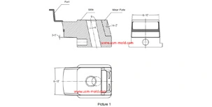
Slider angle designing tips
Dec 4, 20231. Normally, all the insertion slopes of the slider are not allowed to be less than 3° to prevent excessive self-locking force and scratched; 2. The angle of the locking surface must be bigger than...view