 English
 русский

Banana gate of plastic injection mold runner system design
In order to get the best injection quality, the gate type must be selected carefully, the coommon gate tyeps are: direct gate, side gate, pin-point gate, sub gate,valve gate of hot runner etc. Among them, the side gate is divided into tab gate, ear protection gate, fan gate, thin gate and so on, the sub gate is divided into sub gate, banana gate, downturning gate and so on.
According to the production automation, it is divided into manual removal and automatic removal, the side gate and direct gate need to be manually removed after production, but the sub gate pin-point gate, and valve gate of the hot runner are automatically removed.
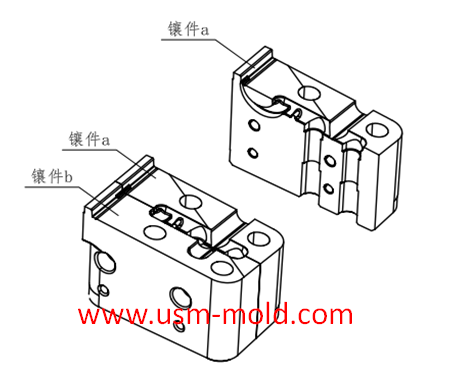
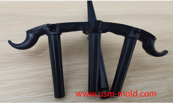
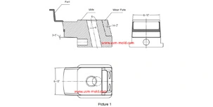
Banana gate: the banana gate is evolved from the sub gate (as shown in picture 1) because it is shaped like the horn of a cow, it is also commonly known as the sub gate, it has a similar hold to the sub gate, the difference is that the processing of the banana gate is more complicated, and it is generally necessary to make a gate insert (as shown in picture 2), the opening of the mold elbow can automatically pull off the gate and the gate position, and also the banana gate can only enter the core, and cannot be made on the side of the product like a sub gate.
Advantage:
1. Made by a professional injection molding supplier, the gate can be cut off automatically, eliminating the secondary processing and realizing automated production;
2. The position of the gate is big, and the position of the gate can be set freely on the outside or inside of the product;
3. The gate is small, which has little effect on the appearance of the product, and some sub-gates are hard to see with eyes;
4. The mold structure can be simplified, for some products with high appearance requirements, if you use the pin-point gate, we must use a three-plate mold to realize it, but we only need to make a two-plate mold if changing to sub gate which can reduce the complexity of the mold structure, but also reduces the mold thickness and saving mold cost.
Disadvantage:
1. Large pressure loss, because the sub gate is generally relatively small, usually in the range of Ø0.8~2.0mm, when the plastic passes through the small gate, a large part of the pressure will be lost;
2. The processing is more complicated, such small gates generally need to make gate inserts;


Slider angle designing tips
Dec 4, 20231. Normally, all the insertion slopes of the slider are not allowed to be less than 3° to prevent excessive self-locking force and scratched; 2. The angle of the locking surface must be bigger than...view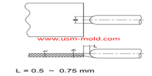
Plastic injection mold runner system design
Jan 16, 2022The gate is the connecting part between the runner and the cavity, and is also the end part of the injection mold gating system, the molten plastic enters the cavity and core side through the gate...view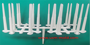
Pin-point gate of plastic injection mold runner system design
Jan 24, 2022In order to get the best injection quality, the gate type must be selected carefully, the coommon gate tyeps are: direct gate, side gate, pin-point gate, sub gate,valve gate of hot runner etc. Among...view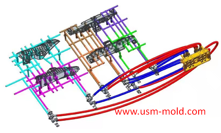
Temperature system of injection mold
Feb 8, 2022Hi everyone,the mold cooling time is the longest during injection, so the design of mold temperature system controlling is very important, we will talk about mold cooling, heating system in following...view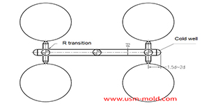
Key points of plastic injection mold runner system
Jan 12, 2022The sub-runner is a transitional channel between the main runner and the gate, as the sub-runner is the longgest part of gating system, so it is very important to enhance the parts quality and improve...view
Plastic injection mold runner system design points
Jan 9, 2022When designing the gating system, Firstly, we should consider making the plastic melt fill the cavity with core side quickly to reduce pressure and heat loss; secondly, it should be economically...view