 English
 русский

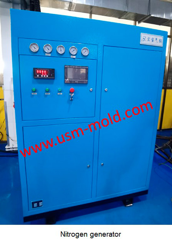
Gas-assisted Injection Molding Equipment
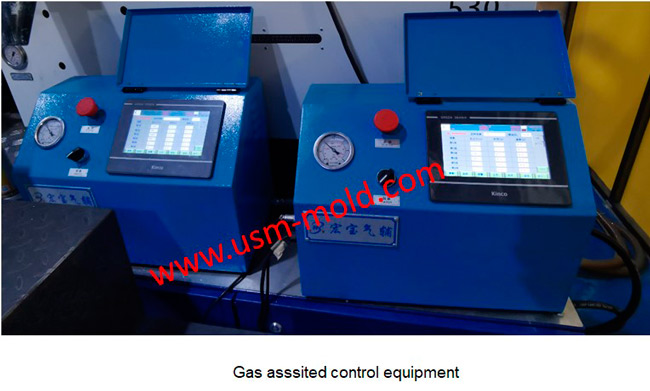
The gas-assisted equipment includes a gas-assisted control part and a nitrogen generator, it is special and seperate system of the injection molding machine, and its only interface with the injection molding machine is the injection signal connection line. After the injection molding machine transmits an injection signal injection start or screw position to the gas-assisted control unit, it starts a gas injection process, and when the next injection process starts, another injection signal is given, and another cycle starts and so on. The gas used in gas-assisted injection molding must be an inert gas (usually nitrogen), the maximum pressure of the gas is 35MPa, and the maximum pressure of the gas can be up to 70MPa, and the nitrogen purity is ≥98%. The gas-assisted control part is a device that controls the gas injection time and pressure, it has a multi-group gas circuit design that can control the gas-assisted production of multiple injection molding machines at the same time, the gas-assisted control part has a gas recovery function to reduce gas as much as possible consumption.

_20250310164515A048.webp "Plastic Box Mould")
_20250311083139A052.webp "Transparent PC Injection Mold")
Design principle of plastic injection mold cooling system
Feb 13, 2022Design principle of cooling system In order to improve the efficiency of the cooling system and make the cavity surface temperature distribution even, the following principles should be followed in...view
Plastic injection mold heating
Feb 16, 2022When the plastic injection molding process requires the mold temperature to be above 80°C, a temperature adjustment system with heating function must be provided in the mold. In addition,...view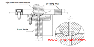
The main design points of the design of the plastic mold pouring system
Jan 11, 2022The main runner is the part where the molten plastic first passes when it is sprayed from the injection nozzle, and it is coaxial with the injection nozzle, because of repeated contact and collision...view_20250317091113A018.jpg)
The basic points of designing gas-assisted injection molding
Apr 17, 20221. Firstly, considering the suitable wall thickness areas needs to be injected and hollowed out, and then decide how to connect them with the gas channel; 2. The gas channel should be arranged in...view
Unique Solutions Mold Profile
Dec 27, 2021USM (UNIQUE SOLUTIONS MOLD LIMITED) was founded in 2012 and is located in Dongguan City, Guangdong Province, a famous mold manufacturing province in China, the plant covers an area of 3500 square...view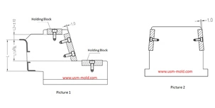
The design requirements of slider wear plate
Jan 2, 20241. The wear plate of slider requires hardening treatment, with a hardness of 45-48HRC; 2. The friction surface of the wear plate is required to be 1.0mm higher than the slider surface (see picture-1);...view