 English
 русский

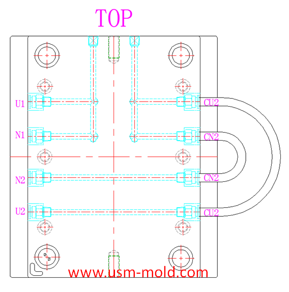
Different treatment of plastic injection mold cooling system principles
Different treatment principle:
1. The mold temperature is different according to the different plastics, when the plastic requires the molding temperature of the mold to be ≥80°C, the mold must be heated.
2. The temperature of the cavity should be higher than the temperature of the core, and the temperature difference is generally 20~30℃.
3. For texture cavity with EDM markson the surface, the cavity temperature should be higher than the general polishing surface, when the cavity must be filled with hot water or hot oil, the general temperature difference is about 40 ℃.
4. For plastic parts with dense meshes, such as speaker shell, the material flow resistance in the mesh area is relatively big and it is difficult to fill. Increasing the mold temperature in this area can improve the filling conditions, the cooling channel in the mesh area is required to be separated from the cooling channel in other areas to flexibly adjust the mold temperature.
5. The mold temperature also depends on the surface quality of the plastic part and the structure of the mold, when designing the temperature control system, it should be targeted from the perspective of the wall thickness of the plastic part, the thick wall should be cooled to prevent shrinkage and deformation; Considering the complexity, cooling should be strengthened at the place where the cavity height fluctuates greatly; the heat of the gate inserts should be strengthened; the cooling channel should be avoided as far as possible through the location of the weld line and the location of the thin wall to prevent the defect more obvious.
6. When the mold temperature is required to be high, such as 70°C or higher, the temperature control of the mold should pay attention to the following:
a. The choice of mold material requires high wear resistance and hardness, heat treatment must be carried out, and the machinability before heat treatment is good.
b. The sealing ring in the mold cooling system should be made of heat-resistant material which is to add the lead.
c. It needs to be a cooling channel between the sliding parts of the mold (such as guide pillar, guide sleeves, etc.) to prevent thermal expansion and contraction from causing movement of moving parts to lock.
d. The shutting-off part of the mold will also strain the shutting-off surface due to thermal expansion and contraction, the shutting-off angle can be appropriately increased to reduce the shutting area, the peripheral interface is formed by inserting.


_20250310164515A048.webp "Visual Doorbell Housing Mold")
Plastic cooling factors by injection parameter
Feb 10, 20221. Plastic parts design: mainly for the wall thickness of plastic products. The thicker thickness of the product, the longer the cooling time. Generally speaking, the cooling time is approximately...view
Plastic injection mold heating
Feb 16, 2022When the plastic injection molding process requires the mold temperature to be above 80°C, a temperature adjustment system with heating function must be provided in the mold. In addition,...view
Plastic injection mold cooling system design notice
Feb 14, 2022Design notice of designing the cooling system: 1. Normal molds can be quickly cooled to obtain a shorter molding cycle, and precision molds can be slowly cooled with a mold temperature thermometer; 2....view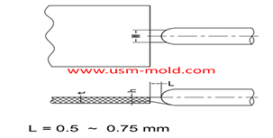
Plastic injection mold runner system design
Jan 16, 2022The gate is the connecting part between the runner and the cavity, and is also the end part of the injection mold gating system, the molten plastic enters the cavity and core side through the gate...view
Plastic part ribs desigining
Jan 4, 2022The ribs function: The role of ribs is to improve the strength and rigidity of the plastic parts, prevent the plastic parts from being distorted and deformed, and will not cause the appearance of the...view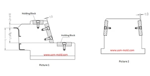
The design requirements of slider wear plate
Jan 2, 20241. The wear plate of slider requires hardening treatment, with a hardness of 45-48HRC; 2. The friction surface of the wear plate is required to be 1.0mm higher than the slider surface (see picture-1);...view