 English
 русский

Slider of side core pulling mechanisum assembling
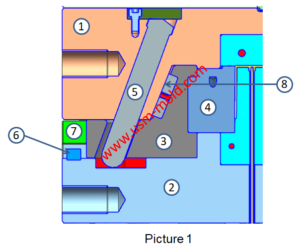
The picture 1 shows a typical guide pin driven slider parting and core-pulling mechanism, we will talk about the composition and function of the lateral core-pulling mechanism.
1. Lateral forming parts: the lateral forming part is the lateral concavo-convex (including the side hole-shaped parts, including the lateral cores and forming blocks, etc.) of the molded plastic parts, such as the slider insert 4 in picture 1;
2. Moveable parts: moveable parts refer to the parts that install and drive the lateral forming blocks or cores and move inside the guide pin, such as the slider which shows in picture 1;
3. Transmission parts: the transmission parts refer to the parts that drive the moving parts for side parting when the mold is opened or to reset when the mold is drawn and closed, such as the inclined angular pin 5 in picture 1, the types of transmission parts are: dog-leg CAM drive, hydraulic cylinder drive, air cylinder drive, etc.;
4. Locking parts: in order to prevent the moving parts from being displaced by lateral pressure during injection, the parts set are called locking parts, such as the wedge tightening surface 8 in picture 1;
5. Limiting parts: in order to make the moving parts stay in the required position after the side parting or core pulling, to ensure that the transmission parts can be reset smoothly when the mold is closed, the moving parts must be set in the lateral direction, the limit parts at the end of parting or lateral core pulling, such as limit block 6 in picture 1;
6. Guide parts: the guide parts refer to the slider that restricts the slider to move in the correct direction when moving, as shown in the guide rails 7 in picture 2.


_20250310164515A048.webp "Touch Switch Sensor Mold")
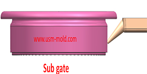
The sub gate of the plastic injection mold runner system
Jan 26, 2022In order to get the best injection quality, the gate type must be selected carefully, the coommon gate tyeps are: direct gate, side gate, pin-point gate, sub gate,valve gate of hot runner etc. Among...view_20250317090912A017.jpg)
Several common process of water-assisted injection molding introduction
May 24, 2022According to the design of the injection molding machine and the casting system, the corresponding melt-returning process of water-assisted injection molding can be roughly divided into two types: the...view
Conformal cooing channel of plastic injection mold
Feb 23, 2022The conformal cooling gate is a new type of mold cooling gate based on 3D printing technolog, because of its processing characteristics, the conformal cooling gate can fit the shape of the product...view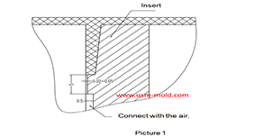
Venting insert design of molded parts
Mar 13, 2022In the thin-walled cavity, the end of the melt flow, the bottom of the blind hole of the mold cavity, the end of the solid column of the plastic part, the bottom of the plastic part rib and screw...view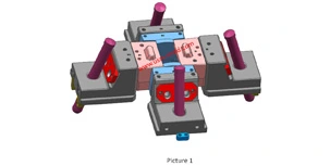
Slider designing tips 2
Nov 22, 20239. The molding parting surface of the slider molding should be made as a shut-off surface as possible, and the width of the shut-off part should be at least 8mm, and do not make a shut-off surface;...view
Vacuum venting mold design for plastic molded parts
Mar 23, 2022There are some regular venting way which are parting surface venting, insert venting, insert pin venting and well-ventilated steel, but there is a special way is vacumm venting, it will need vacumm...view