 English
 русский
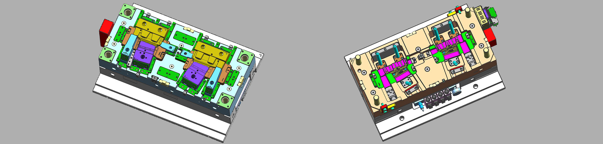
The air trapping position in cavity and exhaust method
The air trapping in cavity is usually in the following places:
1. Thin-wall structure cavity, the end of melt flow;
2. The junction of two or more melts;
3. The last area where the melt in the cavity reaches;
4. The bottom of the blind hole of the mold cavity is mostly the end of a solid column in the part;
5. Reinforcing ribs of molded parts and the bottom of screw pillars;
6. Dead corners of complex mold cavities.
.png)
Exhaust method in injection mold include as following:
1. Parting surface (including venting slot);
2. The fitting surface of insert;
3. The fitting surface of the push rod or pipe with inner mold insert;
4. Exhaust from side core pulling mechanism;
5. Add a vent needle or insert to vent the air in the trapped area;
6. Breathable steel exhaust;
7. Air valve exhaust;
8. The mold is evacuated and exhausted.
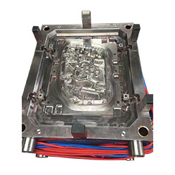
_20250310164515A048.webp "Plastic Box Mould")
Controling method of plastic injection mold temperature
Feb 15, 2022Except for heat radiation and heat convection from the mold, most of the heat bring into the mold by the plastic needs to be taken out of the mold by the circulating heat transfer medium by heat...view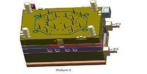
Design Tips of Vacuum Venting Mold
Mar 30, 2022There are some regular venting way which are parting surface venting, insert venting, insert pin venting and well-ventilated steel, but there is a special way is vacumm venting, it will need vacumm...view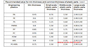
Design principles for wall thickness of plastic products
Jan 3, 2022The principles of wall thickness design for plastic parts are as follows: 1. Making the wall thickness even is the first principle of plastic part design, it can make filling, cooling and shrinking...view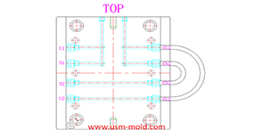
Different treatment of plastic injection mold cooling system principles
Feb 22, 2022Different treatment principle: 1. The mold temperature is different according to the different plastics, when the plastic requires the molding temperature of the mold to be ≥80°C, the mold must be...view
Unique Solutions Mold Profile
Dec 27, 2021USM (UNIQUE SOLUTIONS MOLD LIMITED) was founded in 2012 and is located in Dongguan City, Guangdong Province, a famous mold manufacturing province in China, the plant covers an area of 3500 square...view_20250317090912A017.jpg)
Several common process of water-assisted injection molding introduction
May 24, 2022According to the design of the injection molding machine and the casting system, the corresponding melt-returning process of water-assisted injection molding can be roughly divided into two types: the...view