 English
 русский

Plastic injection mold common cooling gate
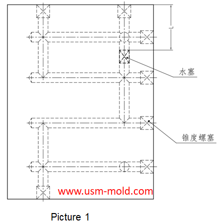
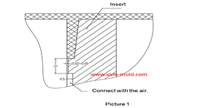
1. Straight-through cooling water gate: the straight-through cooling gate is the most commonly used gate for plastic injection mold, and it is also the most convenient type of cooling for processing. It is commonly used on molds with thinner walls and larger areas, which shows in picture 1.
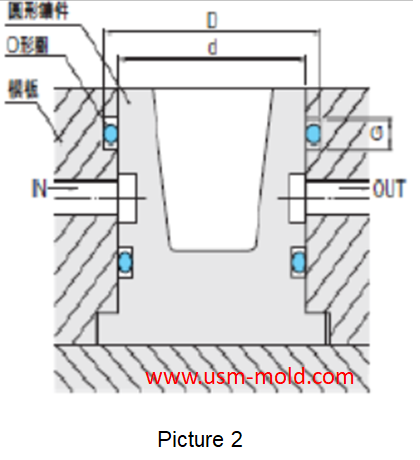
2. Annular cooling water gate: this cooling water gate is suitable for round inserts parts, where there is ejector pin and plastic material in the insert and cannot be used for cooling methods such as water well spraying, the common structure is shown in picture 2, we shold we should try to avoid the sealing ring being worn and worn by the cutting during assembly.
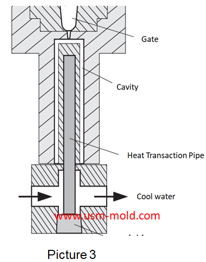
3. Heat conduction rod type: for some slight cores, conventional water transportation, spraying and water well cooling cannot be used, and heat conduction rods can be used to transfer the heat from the melt to the core, and then the cooling water carry out the heat from the mold, as shown in picture 3, the material of the thermal conductive rod is usually beryllium copper.
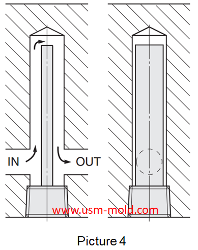
4. Baffle board cooling water gate: the baffle board is often used in deep cavity molds, this type of mold has a large core length and absorbs a lot of heat from the plastic melt, but the width or diameter is small and common, the cooling water gate is often unable to go up, and the ideal effect can be achieved by using a baffle board, as shown in picture 4.
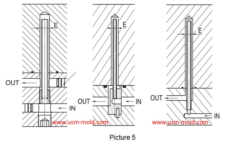
5. Cooling pipe type: the cooling pipe is the same as the baffle board for deep cavity molds, or places where the cooling water channel is difficult to reach but has a large amount of heat accumulation, this kind of cooling water gate needs to use a cooling pipe, it is not as pupular as baffle board in normal design, as shown in picture 5.
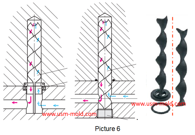
6. Spiaral baffle board: it is normally used as same cooling pipe and baffle board, but the cooling is better, it needs to add spiral pillar or spiral piece, as shown in picture 6.
_20250310164515A048.webp "PLC Controller Shell Mold")


Venting insert design of molded parts
Mar 13, 2022In the thin-walled cavity, the end of the melt flow, the bottom of the blind hole of the mold cavity, the end of the solid column of the plastic part, the bottom of the plastic part rib and screw...view
Direct gate of plastic injection mold runner system design
Jan 19, 2022In order to get the best injection quality, the gate type must be selected carefully, the coommon gate tyeps are: direct gate, side gate, pin-point gate, sub gate,valve gate of hot runner etc. Among...view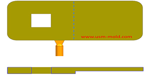
Gate position determination of plastic injection mold runner design system
Jan 17, 2022In the selection of gate location, the following issues should be paid attention to: 1. The gate position should be set at the maximum wall thickness of the plastic part, so that the plastic melt...view_20250317091113A018.jpg)
The basic points of designing gas-assisted injection molding
Apr 17, 20221. Firstly, considering the suitable wall thickness areas needs to be injected and hollowed out, and then decide how to connect them with the gas channel; 2. The gas channel should be arranged in...view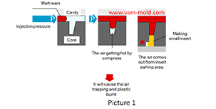
The main reasons for air trapping of plastic injecton mold
Mar 1, 2022During the injection molding process, the front end of the slight ribs may be air trapped and plastic burnt, and also cause the molded part may become black and carbonized. The mechanism of air...view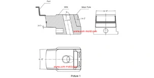
Slider angle designing tips
Dec 4, 20231. Normally, all the insertion slopes of the slider are not allowed to be less than 3° to prevent excessive self-locking force and scratched; 2. The angle of the locking surface must be bigger than...view