 English
 русский

Gate position determination of plastic injection mold runner design system
In the selection of gate location, the following issues should be paid attention to:
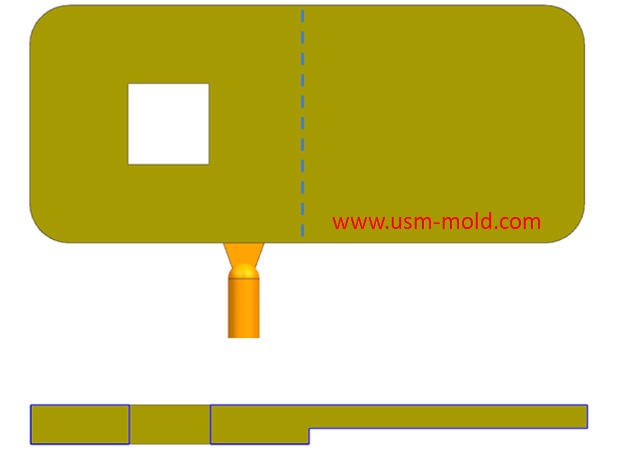
1. The gate position should be set at the maximum wall thickness of the plastic part, so that the plastic melt flows from the thick wall to the thin wall, and the flow from the gate to the cavity is basically the same, as shown in pigure 1. If the plastic melt goes from a narrow area to a thicker or open area, a jet phenomenon will be caused, the jet will not only causee flow marks, but also cause the melt speed and temperature to drop suddenly, thereby affecting the part quality;
2. The gate position should be set in the main force direction of the plastic part, because the tensile stress and compressive stress in the flow direction of the melt are very high, especially for reinforced plastics with glass fiber, this situation is more obvious;
3. When selecting the gate position, the parts size requirements should be considered, because when the plastic melt fills the cavity through the gate, the shrinkage of the plastic part in the melt parallel to the flow direction and perpendicular to the flow direction is not the same, so it should be consider the directionality of plastic deformation and shrinkage.
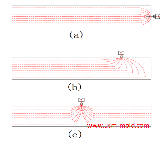
For long and flat plastic parts, the gate position should be selected at one side of plastic part, so that the plastic part obtains a consistent shrinkage in the flow direction, as shown in picture 2(a); if the flow of the plastic part is relatively large, the gate position can be moved a small distance to the middle, as shown in pigure 2(b); but it is not advisable to set the gate position in the middle of the plastic part, it can be seen from picture 2(c) that when the gate is placed in the middle of the plastic part , the resin flow is radial which causing the plastic parts to deform due to uneven radial shrinkage and tangential shrinkage, we will dicuss in following article;
4. When designing the gate, it should be considered to be convenient to remove the gate, and no traces will be left on the plastic part when the gate is corrected, so as to ensure the appearance quality of the plastic part;
5. To avoid welding marks happens on the main surface or affecting the strength of plastic parts, according to the customer's requirements for plastic parts, the weld line is controlled in a more concealed and less stressed position, and also avoid the welding marks to form a line between hole and hole, reducing the strength of the plastic part.
6. Prevent long rod-shaped products from deforming under the action of injection pressure;
7. To avoid affecting the assembly between parts or leaving markson the exposed surface;
8. To prevent the appearance of snake patterns and baking prints, an impact gate or a tab gate should be used;
9. The gate position should be conducive to exhaust;
10. For a multi-cavity mold, the same plastic parts should be fed from the same place, and priority should be given to setting the gate according to the balanced runner arrangement;
11. Consider the efficiency of injection molding production to facilitate the separation of the gating system and the plastic parts, after the mold structure is determined, the gating system and the plastic parts should be considered for easy separation. The use of pin-point gates, sub gates, and arc gates can realize the automatic separation of the runner system and the plastic parts, we should be given to the structure of the plastic part itself when making the location of the sub gate, and also reduce the injection pressure and avoid the difficulty of removing the gate during production. For example, side gates, sub gates, and circular gates are easier to remove, while direct gates, fan gates, and ear guard gates are more difficult to remove;
12. For large and complex products, after selecting the gate position, we generally use mold flow analysis (CAE) software for mold flow analysis to find possible problems in advance.
We will share several common gate types in following articles.


USM Blogo Opening
Oct 27, 2021Hello everyone! Our blog is open today, it is very glad to have the opportunity to meet you here, welcome to visit us whenever you need. USM is a professional plastic injection mold and molding...view
Plastic injection mold heating
Feb 16, 2022When the plastic injection molding process requires the mold temperature to be above 80°C, a temperature adjustment system with heating function must be provided in the mold. In addition,...view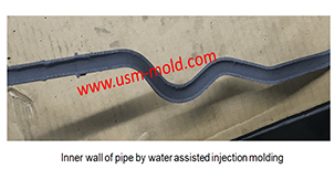
Comparison of water-assisted and gas-assisted injection molding
May 19, 2022Comparing with water-assisted injection molding technology and gas-assisted injection molding technology, the fundamental difference is the nature of the auxiliary molding media used. One is liquid...view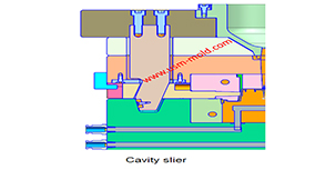
What is the side parting and core pulling mechanisms with their function?
May 31, 2022When there are holes, cavities or cores on the inside or outside of the injection-molded plastic parts that are different from the opening and closing directions of the mold, the plastic parts cannot...view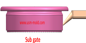
The sub gate of the plastic injection mold runner system
Jan 26, 2022In order to get the best injection quality, the gate type must be selected carefully, the coommon gate tyeps are: direct gate, side gate, pin-point gate, sub gate,valve gate of hot runner etc. Among...view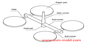
Design principles of plastic injection mold runner system
Jan 6, 20221. Quality first The design of the gating system has a big influence on part quality, firstly the gate should be set at the easiest part of the plastic part to be removed, and at the same time, the...view