 English
 русский

Gas-assisted injection molding product defects and solutions
Common defects and solutions of gas-assisted injection moulding:
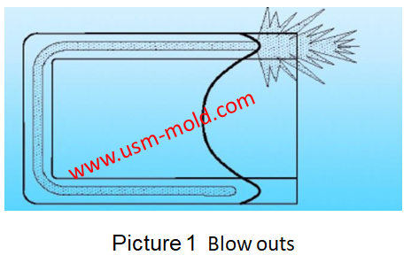
1. Gas blows out the melt like in picture 1.
Reason: insufficient pre-filled amount. When the plastic part is a locally thickened plate-shaped part or a plate with stiffeners, most of the thin plate area should be filled in the pre-filling stage to ensure that the shape of the plastic part is closed and the gas does not break through the melt front. According to our experience, the pre-filled amount of the melt should be higher than 70% of the nominal volume of the plastic part, that is the volume ratio of the hollow part is less than 30%; for thick rod-shaped products, the pre-filled amount accounts for about 6.7%. For simultaneous injection, in order to prevent gas from breaking through, it is also necessary to ensure that there is enough melt in front of the gas injection port during gas injection, so try to start gas injection at the end of pre-filling.
2. There is no cavity or cavity is too small. It is possible to reduce the pre-filling degree, increase the melt temperature and gas pressure, shorten the gas prolong time, extend the gas pressure holding and pressure relief time, select materials with higher fluidity, increase the gas channel, and use the side cavity method. In addition, we can check whether the gas needle is malfunctioning or blocked and whether the gas pipeline is leaking.
3. Sink marks. The methods that can be referred to eliminate sink marks are to reduce the pre-filling degree and melt temperature, increase the pressure of the melt, shorten the gas prolong time, increase the gas pressure, extend the gas pressure relief time, reduce the mould temperature, and increase the gate diameter, runner and gate channel, etc. In addition, the pressure curve in gas injection moulding process can be adjusted to check whether the pipeline and the gas needle are working properly and the weight is not stable enough. Reducing the injection speed, increasing the backpressure, improving the mould pressure and venting, changing the gate position and enlarging the gate are all helpful to overcome this defect.
4. The gate channel wall is too thin. This defect can be overcome by reducing the injection speed, lowering the barrel temperature and gas pressure, extending the gas prolong time, and increasing the gate channel.
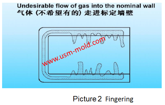
5. Fingering effect as shown in picture 2. Fingering defect means during the blowing process, the bubbles pass through the thin-walled area outside the predetermined airway of the product to form finger-like branches. Severe gas fingering will reduce the strength of plastic products, cause the failure of gas-assisted moulding technology, or fail to take advantage of the advantages of gas-assisted moulding technology. When this phenomenon occurs, you can consider increasing the filling level, reducing the injection speed, barrel temperature and gas pressure, extending the gas prolong time, shortening the gas and pressure relief time, resetting the pressure curve of the gas injection, and selecting the lower fluidity material, lower mould temperature and reduce wall thickness. In addition, the change of gate position and the increase of air passage also helps to improve this defect. The blowing delay time is the most important process condition that affects the gas finger defect, due to the increase of the prolonged time, the plastic melt near the inner wall surface of the mould cavity can be cooled and solidified, and the thickness of the solid layer increases, so that the lateral filling resistance becomes bigger, and the gas follows the resistance, the minimum principle extends longitudinally along the centre of the airway, so that the length of the airway is deepened and the diameter is reduced, and the degree of air finger defects formed by bubbles passing through the thin-walled area outside the airway of the product is reduced. However, if the blowing prolong time is too long, it is easy to cause issues such as unsmooth blowing. Keeping the injection direction consistent with the blowing direction can effectively alleviate the defects caused by excessive blowing prolong the time when making a design.
6. The gas enters the screw of the injection moulding machine. When this issue happens, we can try to increase the melt holding pressure and holding time, reduce the nozzle temperature and gas pressure, shorten the gas holding time and pressure relief time, reset the pressure curve of gas injection, and choose more fluidity Low material, reduce the gate diameter and change the gate position, etc
7. Burst happens after demolding. When this issue happens, we can reduce the gas pressure, extend the pressure holding time, reset the pressure curve of the gas injection, reduce the gas volume, etc., and check whether the gas needle is blocked.
8. Air bubbles on the part surface. The unruptured bubbles on the surface of the part usually appear near the gate, and the diameter of the bubbles is more than 200um. The main difference between bubbles and bumps is that the edges of the bubbles are smoother and often appear as smooth arcs. The causes of bubbles are more complicated, and the trapped air and material degradation during moulding may cause irregular bubbles on the surface of the part. Appropriately lowering the injection temperature and injection speed can alleviate the occurrence of bubbles. However, the lowering of the injection temperature may cause other defects, such as insufficient material and product blow-through, it is necessary to improve the fluidity of the material and use materials with better thermal stability to solve the issue completely.


The design principle of the exhaust slot
Mar 6, 2022The exhaust system of plastic molds is also very important, if the product has air trapping or exhaust system is not suitable will have a big impact on injection molding production and product...view
Plastic cooling factors by injection parameter
Feb 10, 20221. Plastic parts design: mainly for the wall thickness of plastic products. The thicker thickness of the product, the longer the cooling time. Generally speaking, the cooling time is approximately...view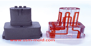
Conformal cooing channel of plastic injection mold
Feb 23, 2022The conformal cooling gate is a new type of mold cooling gate based on 3D printing technolog, because of its processing characteristics, the conformal cooling gate can fit the shape of the product...view
Unique Solutions Mold Profile
Dec 27, 2021USM (UNIQUE SOLUTIONS MOLD LIMITED) was founded in 2012 and is located in Dongguan City, Guangdong Province, a famous mold manufacturing province in China, the plant covers an area of 3500 square...view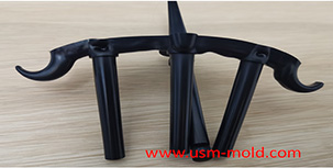
Banana gate of plastic injection mold runner system design
Feb 7, 2022In order to get the best injection quality, the gate type must be selected carefully, the coommon gate tyeps are: direct gate, side gate, pin-point gate, sub gate,valve gate of hot runner etc. Among...view
Slider designing tips 1
Aug 3, 20221. After the slider core pulls out, the length of staying in the guide pin slot should not be less than 2/3 of the total length of the slider, for special cases, the slider slot can be partially...view