 English
 русский

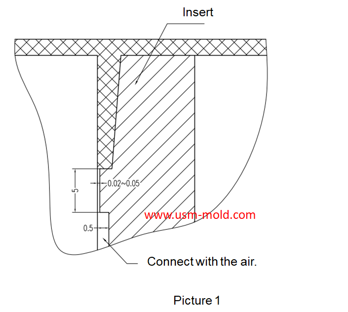
Venting insert design of molded parts
In the thin-walled cavity, the end of the melt flow, the bottom of the blind hole of the mold cavity, the end of the solid column of the plastic part, the bottom of the plastic part rib and screw column, and the corners of the complex cavity are the most where it is easy to cause air trapping, the exhaust in these area mainly depends on the exhaust slot on the shut-off surface between the inserts and the exhaust slot.
Venting design of molded parts:
a. When the end of the material flow is not on the parting surface due to the restriction of the cavity structure, the matching gap between the molded parts can be used to exhaust;
b. Some parts of the forming parts that constitute the cavity, such as ejector rods, ejector pines, moveble parts, etc., the cavity or core are mostly used for clearance fit, and the matching gap is large, if it is designed in the end side of material flow, it can also serve as an exhaust gas, and there is no need to set up an exhaust system at this time;
C. When the exhaust rate cannot meet the requirements, an exhaust structure can be set on the corresponding parts to increase the exhaust rate (see the picture as below);
d. The transitional fitting inserts should have an exhaust slot at the end of the material flow in advance (see the picture as below);
e. The three-stage exhaust slot must be open to the outside of the mold and connected with the air;
f. The exhaust slot between the inserts is easily blocked by plastic powder or mark, and must be cleaned regularly.


Limitations of gas-assisted injection molding technology
Apr 25, 2022Gas-assisted injection molding technology has obvious advantages in thick wall thickness and pipe parts, but this technology still has many limitations, which are mainly reflected in the following...view
Five Major Steps of the Injection Mold Production Process
Dec 9, 2021Injection mold manufacturing can be roughly divided into the following steps: Process analysis of plastic products. Before the mold design, the designer should fully analyze and study whether the...view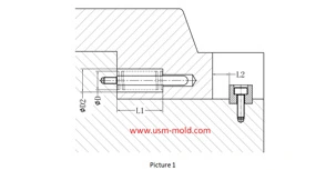
Slider spring hength and strength calculation
Apr 22, 2024Processing size: 1. ØD2=ØD+2 2. Ll = total spring length (L) - preload value of spring (N) - slider core pulling distance (L2) Spring length calculation: (refer to picture 1 for length calculation)...view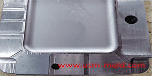
Venting system of plastic injection mold introduction
Feb 27, 2022Hello everyone, thanks for attention. We’ve discussed about the temperature control system earlier, now we are going to talk about the mold venting information in following 11 articles, from the...view_20250317091228A019.jpg)
Main application of gas-assisted molding technology
Apr 7, 2022Gas-assisted molding has a particularly obvious effect on the material saving of tubular and rod-shaped plastic parts, such as car handles, seat armrests, window frames, and wood-like furniture, the...view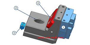
Slider designing tips 1
Aug 3, 20221. After the slider core pulls out, the length of staying in the guide pin slot should not be less than 2/3 of the total length of the slider, for special cases, the slider slot can be partially...view