 English
 русский

Venting insert design of molded parts
In the thin-walled cavity, the end of the melt flow, the bottom of the blind hole of the mold cavity, the end of the solid column of the plastic part, the bottom of the plastic part rib and screw column, and the corners of the complex cavity are the most where it is easy to cause air trapping, the exhaust in these area mainly depends on the exhaust slot on the shut-off surface between the inserts and the exhaust slot.
Venting design of molded parts:
a. When the end of the material flow is not on the parting surface due to the restriction of the cavity structure, the matching gap between the molded parts can be used to exhaust;
b. Some parts of the forming parts that constitute the cavity, such as ejector rods, ejector pines, moveble parts, etc., the cavity or core are mostly used for clearance fit, and the matching gap is large, if it is designed in the end side of material flow, it can also serve as an exhaust gas, and there is no need to set up an exhaust system at this time;
C. When the exhaust rate cannot meet the requirements, an exhaust structure can be set on the corresponding parts to increase the exhaust rate (see the picture as below);
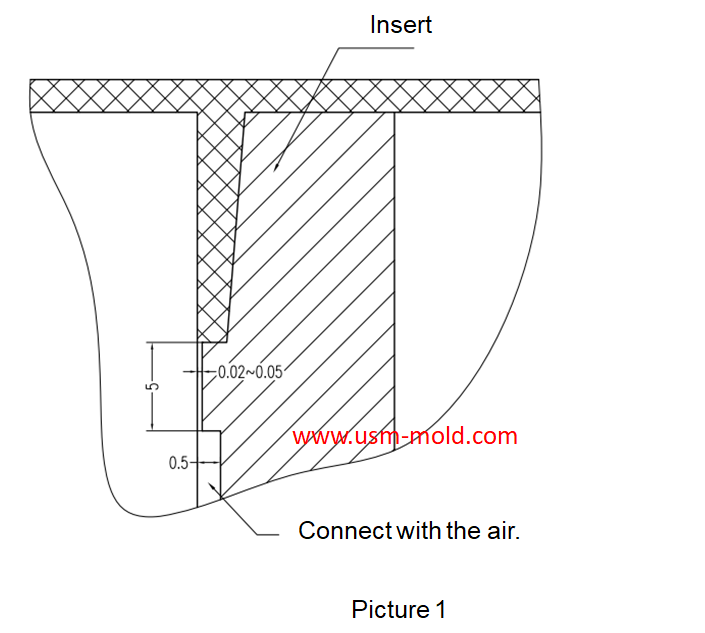
d. The transitional fitting inserts should have an exhaust slot at the end of the material flow in advance (see the picture as below);
e. The three-stage exhaust slot must be open to the outside of the mold and connected with the air;
f. The exhaust slot between the inserts is easily blocked by plastic powder or mark, and must be cleaned regularly.
_20250310164515A048.webp "PLC Controller Shell Mold")


_20250317091228A019.jpg)
Main application of gas-assisted molding technology
Apr 7, 2022Gas-assisted molding has a particularly obvious effect on the material saving of tubular and rod-shaped plastic parts, such as car handles, seat armrests, window frames, and wood-like furniture, the...view
Plastic injection mold runner system design points
Jan 9, 2022When designing the gating system, Firstly, we should consider making the plastic melt fill the cavity with core side quickly to reduce pressure and heat loss; secondly, it should be economically...view
USM Blogo Opening
Oct 27, 2021Hello everyone! Our blog is open today, it is very glad to have the opportunity to meet you here, welcome to visit us whenever you need. USM is a professional plastic injection mold and molding...view
Side gate of plastic injection mold runner system design
Jan 23, 2022In order to get the best injection quality, the gate type must be selected carefully, the coommon gate tyeps are: direct gate, side gate, pin-point gate, sub gate,valve gate of hot runner etc. Among...view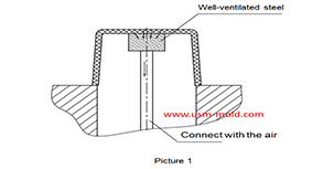
Well-ventilated steel of venting design for molded parts
Mar 14, 2022Well-ventilated steel is a sintered alloy, iIt is a porous material sintered with spherical particle alloys, the pore size is 7-10μm and the strength is poor, but the texture is loose which allow the...view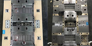
What is Plastic Injection Mold?
Dec 27, 2021The plastic mold is used for injection molding, it is assembled with cavity, core and side slider together, with ejection system and adjustments to produce plastic products by different shapes and...view