 English
 русский

The difference between full shot and short shot of gas-assisted injection molding
Gas-assisted injection molding can be divided into short shot and full shot.
- Short shot
The short shot method is shown in picture 1, it is suitable for thick-walled plastic parts with low mold filling resistance, especially rod-shaped parts, which can save a lot of raw material, we should inject part of resin into the cavity and core (usually only fills 50% volume of caity and core) during the short shot, and immediately inject gas into the center of the resin, push the gas and obtain a hollow plastic part, For thin-walled plastic parts with high mold filling resistance, it’s better to use full shot molding.
For short shots, the percentage and prolong time of plastic melt fills the cavity and core before the gas injected are the main factors to control the length of the gate channel, in addition, the further shrinkage of the plastic will make the channel continue to be longer, if too much plastic is injected at early stage, it will cause the gas flow length is not enough, but if too little plastic is injected, the gas will quickly penetrate the plastic flow front and cause waste.
2. Sub-cavity method (full shot)
The secondary cavity molding method, it is also called the overflow well method, it is a kind of full shot process (as shown in picture 2). the secondary cavity method requires a secondary cavity that can connect with the mold cavity in outside, the secondary cavity follows the main cavity, the valve needle between the cavities is opened or closed by the hydraulic cylinder or air cylinder, first, close the sub cavity, inject plastic melt into the cavity until the cavity and core is full, then open the sub cavity, and inject gas into the cavity, the penetration of gas pressure causes the excess melt to flow into the secondary cavity, when the gas penetrates to a certain extent, the secondary cavity is closed, and the gas pressure continues to increase to maintain pressure and feed the melt in the cavity with core side, and finally open the mold to eject products.


Five Major Steps of the Injection Mold Production Process
Dec 9, 2021Injection mold manufacturing can be roughly divided into the following steps: Process analysis of plastic products. Before the mold design, the designer should fully analyze and study whether the...view
Limitations of gas-assisted injection molding technology
Apr 25, 2022Gas-assisted injection molding technology has obvious advantages in thick wall thickness and pipe parts, but this technology still has many limitations, which are mainly reflected in the following...view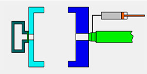
The difference between full shot and short shot of gas-assisted injection molding
Apr 13, 2022Gas-assisted injection molding can be divided into short shot and full shot. Short shot The short shot method is shown in picture 1, it is suitable for thick-walled plastic parts with low mold filling...view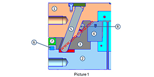
Slider of side core pulling mechanisum assembling
Jul 21, 2022The picture 1 shows a typical guide pin driven slider parting and core-pulling mechanism, we will talk about the composition and function of the lateral core-pulling mechanism. 1. Lateral forming...view
Plastic cooling factors by injection parameter
Feb 10, 20221. Plastic parts design: mainly for the wall thickness of plastic products. The thicker thickness of the product, the longer the cooling time. Generally speaking, the cooling time is approximately...view
Pin-point gate of plastic injection mold runner system design
Jan 24, 2022In order to get the best injection quality, the gate type must be selected carefully, the coommon gate tyeps are: direct gate, side gate, pin-point gate, sub gate,valve gate of hot runner etc. Among...view