 English
 русский

What is the side parting and core pulling mechanisms with their function?
When there are holes, cavities or cores on the inside or outside of the injection-molded plastic parts that are different from the opening and closing directions of the mold, the plastic parts cannot be directly pushed out of the mold by a push mechanism such as a ejector pin. So we will make the movable parts that can move laterally, and then before the plastic parts are demolded and pushed out, the laterally formed parts can be pulled out first, and the plastic parts can be pushed out of the mold, otherwise it cannot be demolded. The entire mechanism that drives the laterally formed parts for lateral splitting and core-pulling and reset is called the lateral splitting and core-pulling mechanism. For the case of forming lateral bosses, it is often called side parting; for forming side holes or undercuts, it is often called side core pulling.
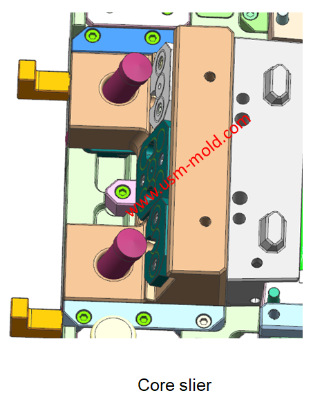
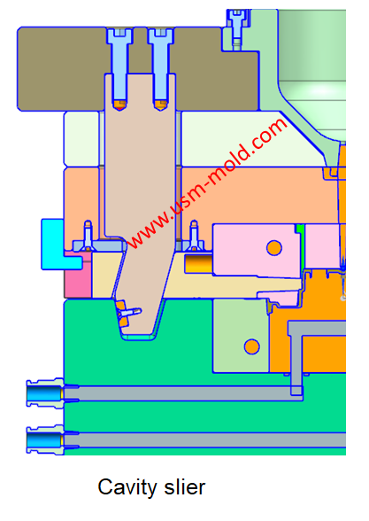
The main function is to get rid of the undercur on the plastic part, so that the plastic part can be smoothly released from the mold. The structures often used in the mold include slider core pulling, lifter core pulling, unscrewing core pulling, etc., and the slider can be subdivided into cavity slider, core slider, inner slider (tunnel slider) and so on.


Gate position determination of plastic injection mold runner design system
Jan 17, 2022In the selection of gate location, the following issues should be paid attention to: 1. The gate position should be set at the maximum wall thickness of the plastic part, so that the plastic melt...view
What is Plastic Injection Mold?
Dec 27, 2021The plastic mold is used for injection molding, it is assembled with cavity, core and side slider together, with ejection system and adjustments to produce plastic products by different shapes and...view
What is Ejection Molding?
Dec 28, 2021The process to get injection molded products is called injection molding, or called injection. Injection molding is an important method in polymer molding processing, it is characterized by a short...view
What is Called Draft Angle?
Dec 29, 2021The draft angle is also called demold angle and angle which is used for product removal from the mold and designed on the parting surface, the angle is called draft angle which shows in picture 1....view
Five Major Steps of the Injection Mold Production Process
Dec 9, 2021Injection mold manufacturing can be roughly divided into the following steps: Process analysis of plastic products. Before the mold design, the designer should fully analyze and study whether the...view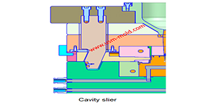
What is the side parting and core pulling mechanisms with their function?
May 31, 2022When there are holes, cavities or cores on the inside or outside of the injection-molded plastic parts that are different from the opening and closing directions of the mold, the plastic parts cannot...view