 English
 русский

Plastic part ribs desigining
The ribs function:
The role of ribs is to improve the strength and rigidity of the plastic parts, prevent the plastic parts from being distorted and deformed, and will not cause the appearance of the product to shrink due to the increased rigidity, and it is also beneficial to the plastic raw materials during injection molding, flow is the best way to reduce the product unit price and increase the strength of the product
In order to ensure the strength and rigidity of the plastic part without causing the wall thickness of the plastic part to be too thick, ribs can be arranged at appropriate positions of the plastic part to avoid deformation, the ribs also serve as the positioning of the assembly components, the role of the matching parts, the stop and guide of the mechanism, and the ribs can also act as an internal flow channel to improve the flow of plastic during the multi cavity injection molding process and help mold cavity filling.
Experience for ribs size designing
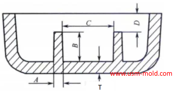
The rib size designing is shown in picture 1 as follwing:
dimension A is the thickness of the large end of the rib, the value range is generally between 0.4 and 0.6T, the value is 1/3 of the main wall thickness, if it is determined to be too thin during the mold review, it can be increased appropriately, dimension B is the rib, the general requirement is not more than 3T, on the premise of meeting the strength and rigidity, the rib height should be as low as possible.
Dimension C is the distance between two reinforcing ribs, the general requirement is not less than 4T, but it is not absolutely necessary to be greater than 4T. For example, two reinforcing ribs need to be designed in the design of the reverse stop, but the distance between the two reinforcing ribs Less than 4T.
Dimension D is the distance between the upper end of the rib and the highest edge of the part, the general requirement is not less than 1.0mm, it can be adjusted according to the actual design, and the highest can be leveled.
Strength calculation of ribs
Calculated according to the cross-section of a flat plastic product, for every 10% increase in the wall thickness, the part’s flatness rigidity will increase by about 33%, for a simple surface, an increase of 25% in thickness can increase the rigidity of the shell by one time, the corresponding intensity is calculated by analogy.
Rib types and layout
At present, the types of reinforcing ribs on the product are strip, well, fan, X, round and comprehensive (comprehensive shape = well shape + round shape + X shape).
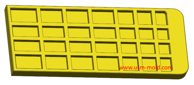
Strip rib
Strip-shaped ribs (as shown in picture 2) are generally designed to have a small area of ribs on the shell, and do not need to bear high-strength loads, only increase the strength of a single shell. If the ribs are too dense, it will affect the strength of the mold, and it is easy to stick to the back mold the core side when inection, the spacing of the strip ribs is determined according to the strength of the mold steel, the thinnest wall thickness of the ultimate mold steel is 0.6mm, and the height does not exceed 2mm, the sharp corners of the mold are not calculated, in the regular structure shape, most molds are made by wire cutting. For processing, if we want to ensure good strength, we need to design the mold wall thickness above 4mm, the rib height does not exceed 8mm, and the subsequent rib position increases by 1mm, the mold wall thickness increases by 1-1.2 times.
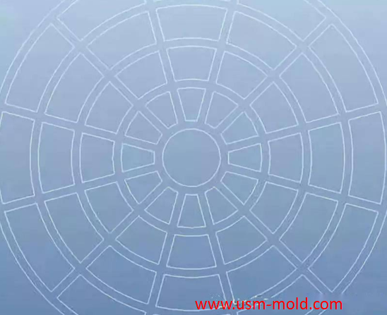
Well-shaped rib/X-shaped rib
Well-shaped rib are generally used on shell parts that can be designed to have a large area of rib (as shown in picture 3) and need to bear high-strength loads, such as display bracket chassis parts, and shell parts that need to bear bending loads.
The distance between the well shape and the X-shaped rib is generally determined according to the strength of the mold steel, the thinnest wall thickness of the ultimate mold steel is 0.6mm, and the height does not exceed 2mm, the sharp corners of the mold are not calculated, in the regular structural shape, most molds use wire for cutting and processing, if we want to ensure good strength, we need to design the mold wall thickness above 4mm, the rib height does not exceed 8mm, and the subsequent rib position increases by 1mm, the mold wall thickness increases by 1-1.2 times.
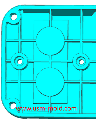
Round/scalloped ribs
The circular and fan-shaped ribs generally have the same space requirements as the well-shaped or X-shaped (as shown in picture 4), the other difference is the stress point, the center of the circular and fan-shaped rib is even. If the center of the product shell is a strong stress point, it is more reasonable to design a circular or fan-shaped rib.
The spacing between the circular and fan-shaped reinforcing ribs is generally determined according to the strength of the mold steel, the thinnest wall thickness of the ultimate mold steel is 0.6mm, and the height does not exceed 2mm, the sharp corners of the mold are not calculated, in the regular structure shape, most molds use wire cutting, if we want to ensure good strength, we need to design the mold wall thickness above 4mm, the rib height does not exceed 8mm, and the subsequent rib position increases by 1mm, the mold wall thickness increases by 1-1.2 times.
Comprehensive shape (comprehensive shape = well shape + circle + X shape)
Comprehensive ribs are mainly used in the following condition:
1. Since the cross section of the well shape and the X shape will have the risk of shrinking during the glue running, which will affect the appearance, the change to the well shape + circular method can improve this shrinkage risk and make the glue running more smoothly (picture 5) shown).
2. Because the mold is ejected, the number of well-shaped and X-shaped ribs is too large, which will make the product easy to stick to the back mold. The design is round, and it can be ejected on the mold by the way of a cylinder, which can avoid the phenomenon of mold sticking.
3. Because of the glue, adding X-shaped ribs in the case of well-shaped + circular ribs can allow the product to take several more channels to make the plastic go faster and smoother, and it can also increase the product strength.


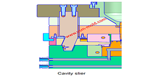
What is the side parting and core pulling mechanisms with their function?
May 31, 2022When there are holes, cavities or cores on the inside or outside of the injection-molded plastic parts that are different from the opening and closing directions of the mold, the plastic parts cannot...view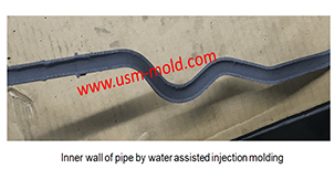
Comparison of water-assisted and gas-assisted injection molding
May 19, 2022Comparing with water-assisted injection molding technology and gas-assisted injection molding technology, the fundamental difference is the nature of the auxiliary molding media used. One is liquid...view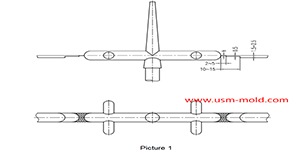
Parting surface venting of runner system
Mar 10, 2022There are a large amount of gas in the main and sub channel, these gas are discharged through the pull rod (push rod) during injection processing, a part of gas come out from exhaust slot on parting...view
Unique Solutions Mold Profile
Dec 27, 2021USM (UNIQUE SOLUTIONS MOLD LIMITED) was founded in 2012 and is located in Dongguan City, Guangdong Province, a famous mold manufacturing province in China, the plant covers an area of 3500 square...view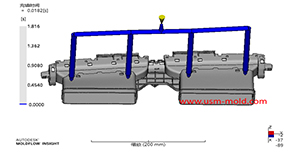
Plastic injection mold runner system design points
Jan 9, 2022When designing the gating system, Firstly, we should consider making the plastic melt fill the cavity with core side quickly to reduce pressure and heat loss; secondly, it should be economically...view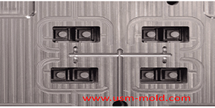
The air trapping position in cavity and exhaust method
Mar 2, 2022The air trapping in cavity is usually in the following places: 1. Thin-wall structure cavity, the end of melt flow; 2. The junction of two or more melts; 3. The last area where the melt in the cavity...view