 English
 русский

Plastic cooling factors by injection parameter
1. Plastic parts design: mainly for the wall thickness of plastic products. The thicker thickness of the product, the longer the cooling time. Generally speaking, the cooling time is approximately proportional to the square of the thickness of the plastic product, or proportional to the 1.6th times of the biggest runner diameter, that is the thickness of the plastic product is doubled, and the cooling time is increased by 4 times.
2. Mold materials and cooling methods: mold materials, including mold core, cavity materials, and mold base materials have a big influence on the cooling rate, the higher the thermal conductivity of the mold material, the better the effect of transferring heat from the plastic per unit time, and the shorter the cooling time.
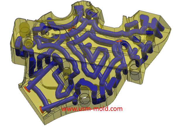
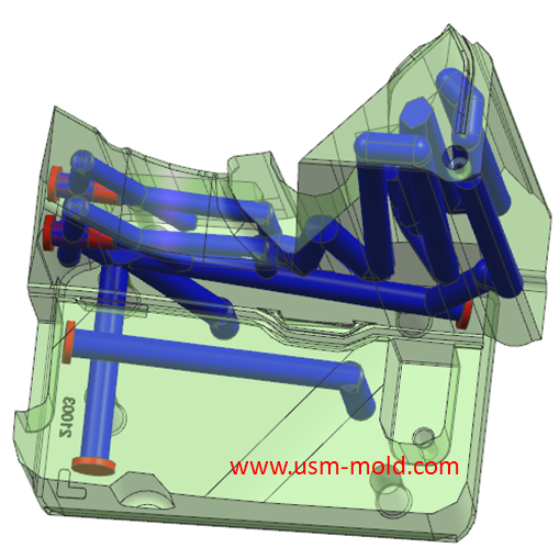
3. Cooling water pipe configuration: the closer the cooling water pipe is to the mold cavity and core, the larger the pipe diameter and the larger the number, the better the cooling effect and the shorter the cooling time.
4. Coolant flow rate: the larger the cooling water flow rate (generally to achieve turbulent flow), the better the effect of cooling water to take away heat by thermal convection.
5. The nature of the coolant: the viscosity and thermal conductivity of the coolant will also affect the heat transfer effect of the mold, the lower the viscosity of the coolant, the higher the thermal conductivity, and the lower the temperature, the better the cooling effect.
6. Plastic selection: plastic refers to the measurement of the speed at which plastic conducts heat from a hot area to a cold area, the higher the thermal conductivity of the plastic, the better the heat conduction effect, or the lower the specific heat of the plastic, the temperature is prone to change, so the heat is easily dissipated, the heat conduction effect is better, and the required cooling time is shorter.
7. Processing parameter setting: the higher the material temperature, the higher the mold temperature, the lower the ejection temperature, and the longer the required cooling time.
8. The designed cooling gate should ensure the cooling effect is even and fast , the purpose of designing the cooling system is to maintain proper and efficient cooling of the mold, cooling holes should use standard sizes to facilitate processing and assembly.
9. When designing the cooling system, the mold designer must determine the following design parameters based on the wall thickness and volume of the plastic part-the location and size of the cooling hole, the length of the hole, the type of hole, the configuration and connection of the hole, and the flow of cooling liquid speed and heat transfer properties.


Hydraulic diameter conversion of runners in plastic mold gating system design
Jan 13, 2022Hydraulic diameter refers to 4 times the ratio of the flow cross-sectional area to the perimeter, as the wall shear stress of non-circular pipes is not even distributed along the surrounding walls,...view
Plastic injection mold runner system design
Jan 16, 2022The gate is the connecting part between the runner and the cavity, and is also the end part of the injection mold gating system, the molten plastic enters the cavity and core side through the gate...view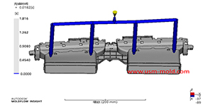
Plastic injection mold runner system design points
Jan 9, 2022When designing the gating system, Firstly, we should consider making the plastic melt fill the cavity with core side quickly to reduce pressure and heat loss; secondly, it should be economically...view
What is Ejection Molding?
Dec 28, 2021The process to get injection molded products is called injection molding, or called injection. Injection molding is an important method in polymer molding processing, it is characterized by a short...view
Design principles for wall thickness of plastic products
Jan 3, 2022The principles of wall thickness design for plastic parts are as follows: 1. Making the wall thickness even is the first principle of plastic part design, it can make filling, cooling and shrinking...view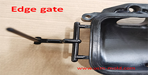
Side gate of plastic injection mold runner system design
Jan 23, 2022In order to get the best injection quality, the gate type must be selected carefully, the coommon gate tyeps are: direct gate, side gate, pin-point gate, sub gate,valve gate of hot runner etc. Among...view