 English
 русский

The air trapping position in cavity and exhaust method
The air trapping in cavity is usually in the following places:
1. Thin-wall structure cavity, the end of melt flow;
2. The junction of two or more melts;
3. The last area where the melt in the cavity reaches;
4. The bottom of the blind hole of the mold cavity is mostly the end of a solid column in the part;
5. Reinforcing ribs of molded parts and the bottom of screw pillars;
6. Dead corners of complex mold cavities.
.png)
Exhaust method in injection mold include as following:
1. Parting surface (including venting slot);
2. The fitting surface of insert;
3. The fitting surface of the push rod or pipe with inner mold insert;
4. Exhaust from side core pulling mechanism;
5. Add a vent needle or insert to vent the air in the trapped area;
6. Breathable steel exhaust;
7. Air valve exhaust;
8. The mold is evacuated and exhausted.

_20250310164515A048.webp "PLC Controller Shell Mold")

_20250317090912A017.jpg)
Several common process of water-assisted injection molding introduction
May 24, 2022According to the design of the injection molding machine and the casting system, the corresponding melt-returning process of water-assisted injection molding can be roughly divided into two types: the...view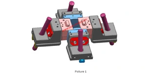
Slider designing tips 2
Nov 22, 20239. The molding parting surface of the slider molding should be made as a shut-off surface as possible, and the width of the shut-off part should be at least 8mm, and do not make a shut-off surface;...view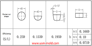
Hydraulic diameter conversion of runners in plastic mold gating system design
Jan 13, 2022Hydraulic diameter refers to 4 times the ratio of the flow cross-sectional area to the perimeter, as the wall shear stress of non-circular pipes is not even distributed along the surrounding walls,...view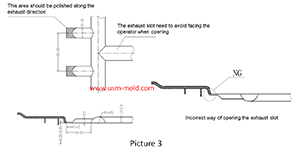
Design standard of exhaust slot
Mar 3, 2022The exhaust system should ensure that the gas in the cavity is smoothly discharged, and also prevent the material from entering and exhausting channels from causing flashing of the product or blockage...view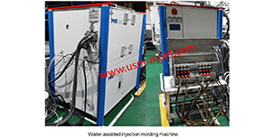
Water assisted injection molding introduction
May 11, 2022Like the gas-assisted injection molding process, water-assisted injection molding injects a piece of plastic into the mold cavity and core firstly, and then injects water to squeeze the melt plastic...view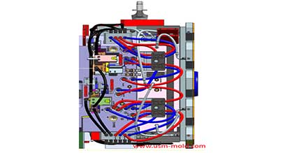
Plastic injection mold cooling system design notice
Feb 14, 2022Design notice of designing the cooling system: 1. Normal molds can be quickly cooled to obtain a shorter molding cycle, and precision molds can be slowly cooled with a mold temperature thermometer; 2....view