 English
 русский

Design principle of plastic injection mold cooling system
Design principle of cooling system
In order to improve the efficiency of the cooling system and make the cavity surface temperature distribution even, the following principles should be followed in the design of the cooling system:
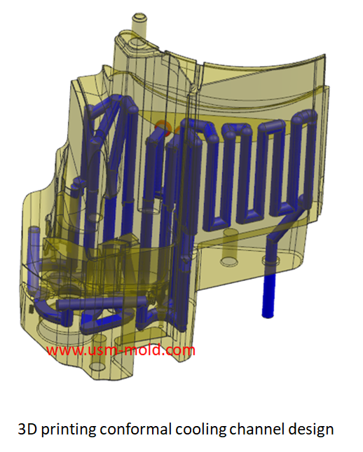
1. When designing the mold, the cooling method and the location of the cooling circuit should be considered first, and there should be enough space. The water flow in the cooling hole should be turbulent, the setting of the cooling water circuit should meet the needs of the molding process, and there should be sufficient, even and balanced cooling effect;
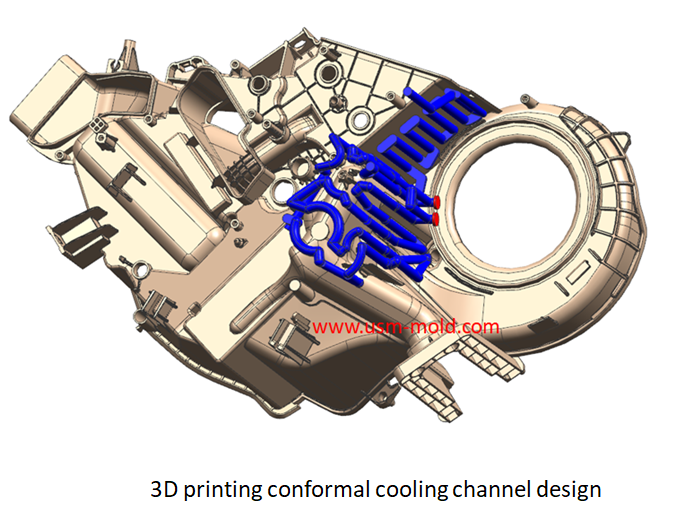
2. Considering the temperature difference between the inlet and outlet, the flow pressure drop (calculate the pipe diameter and length). Reduce the temperature difference between the inlet and outlet of the cooling water (5°C for general molds and 2°C for precision molds). The length of the cooling circuit is below 1.2-1.5m, the flow rate is controlled within the range of 0-1.0m/s, and the number of elbows in the circuit does not exceed 15, when the water barrier is connected in series, the number of turns is a set of 4 times. For medium and large molds, the cooling water pipe can be divided into several independent circuits to increase the flow of coolant, reduce pressure loss, and improve transmission efficiency, the cooling effect of using multiple and thin cooling pipes is better than that of a single large-diameter pipe;
3. The number of cooling water holes is as more as possible, and the hole diameter is as big as possible (the size is selected according to the shape characteristics of the plastic part and the mold structure, the inner diameter of the water pipe and the pipe connector should be equal to the diameter of the cooling hole), the number, the interval and the distance to the surface of the molding space Has a significant impact on the control of mold temperature;
4. The mold temperature which near the gate is higher, and the cooling circuit should be arranged from the inside (near the gate) to the outside (far from the gate), the main runner part of the mold is often in contact with the nozzle of the injection machine, and the temperature near the gate is high, so cooling should be strengthened, and a separate cooling channel should be designed when necessary;
5. because the temperature at the weld mark is the lowest, avoid setting the cooling pipe at the welded part of the product, otherwise the temperature will drop, the weld mark will be more obvious, and the weld strength of the plastic part will be lower;
6. The water inlet and outlet pipe joints should be located on the side of the reverse operation surface;
7. The cooling circuit of the mold cavity and core side should be separated, pay attention to the cooling balance between the cavity and the core, so the designer should pay special attention to the cooling effect of the core, and ensure that the plastic part is fully cooled and shrinking balance. The designer should be very careful to the cooling effect of the cavity and core, and the product should be fully cooled and shrinking balanced.


Side gate of plastic injection mold runner system design
Jan 23, 2022In order to get the best injection quality, the gate type must be selected carefully, the coommon gate tyeps are: direct gate, side gate, pin-point gate, sub gate,valve gate of hot runner etc. Among...view
Unique Solutions Mold Profile
Dec 27, 2021USM (UNIQUE SOLUTIONS MOLD LIMITED) was founded in 2012 and is located in Dongguan City, Guangdong Province, a famous mold manufacturing province in China, the plant covers an area of 3500 square...view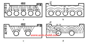
Factors affecting the cooling rate of parts by injection molding
Feb 9, 2022It should be shaped by cooling to get stable plastic part after plastic filling the cavity and core side, so most injection molds need to be equipped with cooling devices to make the mold temperature...view
Banana gate of plastic injection mold runner system design
Feb 7, 2022In order to get the best injection quality, the gate type must be selected carefully, the coommon gate tyeps are: direct gate, side gate, pin-point gate, sub gate,valve gate of hot runner etc. Among...view
Plastic part ribs desigining
Jan 4, 2022The ribs function: The role of ribs is to improve the strength and rigidity of the plastic parts, prevent the plastic parts from being distorted and deformed, and will not cause the appearance of the...view
Five Major Steps of the Injection Mold Production Process
Dec 9, 2021Injection mold manufacturing can be roughly divided into the following steps: Process analysis of plastic products. Before the mold design, the designer should fully analyze and study whether the...view